MSI P45D3 User Guide - Page 33
Front USB Connector: JUSB1 ~ 3
 |
View all MSI P45D3 manuals
Add to My Manuals
Save this manual to your list of manuals |
Page 33 highlights
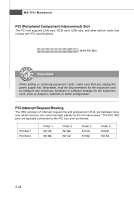
Hardware Setup Front USB Connector: JUSB1 ~ 3 These connectors, compliant with Intel® I/O Connectivity Design Guide, is ideal for connecting high-speed USB interface peripherals such as USB HDD, digital cameras, MP3 players, printers, modems and the like. JUSB1~3 2 10 1 9 Pin Definition PIN SIGNAL 1 VCC 3 USB0- 5 USB0+ 7 GND 9 Key (no pin) PIN SIGNAL 2 VCC 4 USB1- 6 USB1+ 8 GND 10 USBOC USB 2.0 Bracket (Optional) connect the YELLOW connector to JUSB1/2/3 Important Note that the pins of VCC and GND must be connected correctly to avoid possible damage. 2-19
-
 1
1 -
2
-
3
-
4
-
5
-
6
-
7
-
8
-
9
-
10
-
11
-
12
-
13
-
14
-
15
-
16
-
17
-
18
-
19
-
20
-
21
-
22
-
23
-
24
-
25
-
26
-
27
-
 28
28 -
 29
29 -
 30
30 -
 31
31 -
 32
32 -
 33
33 -
 34
34 -
 35
35 -
 36
36 -
 37
37 -
 38
38 -
39
-
40
-
41
-
42
-
43
-
44
-
45
-
46
-
47
-
48
-
49
-
50
-
51
-
52
-
53
-
54
-
55
-
56
-
57
-
58
-
59
-
60
-
61
-
62
-
63
-
64
-
65
-
66
-
67
-
68
-
69
-
70
-
71
-
72
-
73
-
74
-
75
-
76
-
77
-
78
-
79
-
80
-
81
-
82
-
83
-
84
-
85
-
86
-
87
-
88
-
89
-
90
-
91
-
92
-
93
-
94
-
95
-
96
-
97
-
98
-
99
-
100
-
101
-
102
-
103
-
104
-
105
-
106
-
107
-
108
-
109
-
110
-
111
-
112
-
113
-
114
-
115
-
116
-
117
-
118
-
119
-
120
-
121
-
122
-
123
-
124
-
125
-
126
-
127
-
128
-
129
-
130
-
131
-
132
-
133
-
134
-
135
-
136
-
137
-
138
-
139
-
140
-
141
 |
 |

2-19
Hardware Setup
Front USB Connector: JUSB1 ~ 3
These connectors, compliant with Intel
®
I/O Connectivity Design Guide, is ideal for
connecting high-speed USB interface peripherals such as
USB HDD
,
digital cameras
,
MP3 players
,
printers
,
modems and the like
.
1
2
9
10
JUSB1~3
PIN
SIGNAL
PIN
SIGNAL
1
VCC
2
VCC
3
USB0-
4
USB1-
5
USB0+
6
USB1+
7
GND
8
GND
9
Key (no pin)
10
USBOC
Pin Definition
Important
Note that the pins of VCC and GND must be connected correctly to avoid
possible damage.
USB 2.0 Bracket
(Optional)
connect the YELLOW connector to JUSB1/2/3