MSI P6NGM User Guide - Page 28
Chassis Intrusion Connector: JCI1, S/PDIF-Out Connector: JSP1 2pin, 3pin optional, CD-In Connector:
 |
View all MSI P6NGM manuals
Add to My Manuals
Save this manual to your list of manuals |
Page 28 highlights
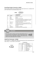
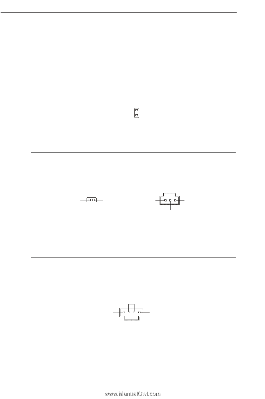
Hardware Setup Chassis Intrusion Connector: JCI1 This connector connects to the chassis intrusion switch cable. If the chassis is opened, the chassis intrusion mechanism will be activated. The system will record this status and show a warning message on the screen. To clear the warning, you must enter the BIOS utility and clear the record. CINTRU 1 GND 2 JCI1 S/PDIF-Out Connector: JSP1 (2pin, 3pin optional) This connector is used to connect S/PDIF (Sony & Philips Digital Interconnect Format) interface for digital audio transmission. SPDIFO GND JSP1 (2pin, for HDM I graphics card) VCC GND SPDIF JSP1 (3pin) CD-In Connector: JCD1 This connector is provided for external audio input. GND L R JCD1 2-13
-
 1
1 -
2
-
3
-
4
-
5
-
6
-
7
-
8
-
9
-
10
-
11
-
12
-
13
-
14
-
15
-
16
-
17
-
18
-
19
-
20
-
21
-
22
-
 23
23 -
 24
24 -
 25
25 -
 26
26 -
 27
27 -
 28
28 -
 29
29 -
 30
30 -
 31
31 -
 32
32 -
 33
33 -
34
-
35
-
36
-
37
-
38
-
39
-
40
-
41
-
42
-
43
-
44
-
45
-
46
-
47
-
48
-
49
-
50
-
51
-
52
-
53
-
54
-
55
-
56
-
57
-
58
-
59
-
60
-
61
-
62
-
63
-
64
-
65
-
66
-
67
-
68
-
69
-
70
-
71
-
72
-
73
-
74
-
75
-
76
-
77
-
78
-
79
-
80
-
81
-
82
-
83
-
84
-
85
-
86
-
87
-
88
-
89
-
90
-
91
-
92
-
93
-
94
-
95
-
96
-
97
-
98
-
99
-
100
-
101
-
102
-
103
-
104
-
105
-
106
-
107
-
108
 |
 |
2-13
Hardware Setup
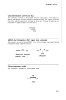
Chassis Intrusion Connector: JCI1
This connector connects to the chassis intrusion switch cable. If the chassis is
opened, the chassis intrusion mechanism will be activated. The system will record
this status and show a warning message on the screen. To clear the warning, you
must enter the BIOS utility and clear the record.
JCI1
2
CINTRU
GND
1
S/PDIF-Out Connector: JSP1 (2pin, 3pin optional)
This connector is used to connect S/PDIF (Sony & Philips Digital Interconnect Format)
interface for digital audio transmission.
SPDIFO
GND
VCC
SPDIF
GND
JSP1 (2pin, for HDMI
graphics card)
JSP1 (3pin)
CD-In Connector: JCD1
This connector is provided for external audio input.
JCD1
GND
R
L