MSI PX8 NEO-V User Guide - Page 19
Connectors - audio
 |
View all MSI PX8 NEO-V manuals
Add to My Manuals
Save this manual to your list of manuals |
Page 19 highlights
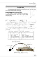
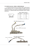
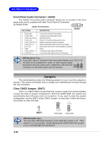
Hardware Setup Connectors The mainboard provides connectors to connect to FDD, IDE HDD, case, USB Ports and CPU/System/Power Supply FAN. Floppy Disk Drive Connector: FDD1 The mainboard provides a standard floppy disk drive connector that supports 360K, 720K, 1.2M, 1.44M and 2.88M floppy disk types. FDD1 S-Bracket (SPDIF) Connector: JSP1 (Optional) The connector allows you to connect a S-Bracket for Sony & Philips Digital Interface (SPDIF). The S-Bracket offers 2 SPDIF jacks for digital audio transmission (one for optical fiber connection 2 12 and the other for coaxial), and 2 analog Line-Out jacks for 4- 1 11 channel audio output. JSP1 To attach the fiber-optic cable to optical SPDIF jack, you need to remove the plug from the jack first. The two SPDIF jacks support SPDIF output only. JSP1 Pin Definition PIN SIGNAL DESCRIPTION PIN SIGNAL DESCRIPTION 1 VCC5 VCC 5V 2 VDD3 VDD 3.3V 3 SPDFO S/PDIF output 4 (No Pin) Key 5 GND Ground 6 SPDFI S/PDIF input 7 LFE-OUT Audio bass output 8 SOUT-R Audio right surrounding output 9 CET-OUT Audio center output 10 SOUT-L Audio left surrounding output 11 GND Ground 12 GND Ground Optional S-Bracket Connect to JSP1 Analog Line-Out SPDIF jack (optical) SPDIF jack (coaxial) 2-7
-
 1
1 -
2
-
3
-
4
-
5
-
6
-
7
-
8
-
9
-
10
-
11
-
12
-
13
-
 14
14 -
 15
15 -
 16
16 -
 17
17 -
 18
18 -
 19
19 -
 20
20 -
 21
21 -
 22
22 -
 23
23 -
 24
24 -
25
-
26
-
27
-
28
-
29
-
30
 |
 |
