MSI Z77A User Guide - Page 40
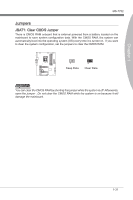
Ground, the Platform Controller Hub.
 |
View all MSI Z77A manuals
Add to My Manuals
Save this manual to your list of manuals |
Page 40 highlights
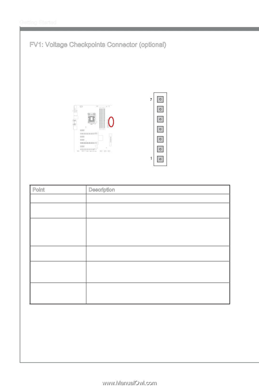
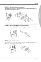
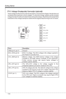
Getting Started FV1: Voltage Checkpoints Connector (optional) These voltage checkpoint are used to measure the current system voltages. A multimeter (not included) will be required to check voltages. To check the voltage, please use the included voltage checkpoint cables included in the mainboard package. Attach the positive lead of the multimeter to the voltage checkpoint cable and the negative lead to the ground connector. 7 GND GND PCH_1P05 VCC_DDR CPU_GFX CPU_VTT 1 VCCP Point GND (pin 6, pin 7) PCH_1P05 (pin 5) VCC_DDR (pin 4) CPU_GFX (pin 3) CPU_VTT (pin 2) VCCP (pin 1) Description Ground PCH 1.5 voltage. The PCH voltage is the voltage supplied to the Platform Controller Hub. Memory voltage. The DDR memory voltage is the voltage supplied to the DDR memory modules on the mainboard. Lower memory timings may require higher voltages to maintain system stability. The CPU_GFX voltage is the voltage supplied to the integrated graphics processor located on the CPU. CPU IO voltage (Uncore). The CPU IO voltage is the voltage supplied to the Uncore on the CPU. Higher overclocks may require a higher CPU IO voltage to maintain stability. CPU core voltage. The CPU voltage is the voltage suppoied to the CPU core. Higher overclocks may require higher CPU core voltages to maintain stability. 1-30
-
 1
1 -
2
-
3
-
4
-
5
-
6
-
7
-
8
-
9
-
10
-
11
-
12
-
13
-
14
-
15
-
16
-
17
-
18
-
19
-
20
-
21
-
22
-
23
-
24
-
25
-
26
-
27
-
28
-
29
-
30
-
31
-
32
-
33
-
34
-
 35
35 -
 36
36 -
 37
37 -
 38
38 -
 39
39 -
 40
40 -
 41
41 -
 42
42 -
 43
43 -
 44
44 -
 45
45 -
46
-
47
-
48
-
49
-
50
-
51
-
52
-
53
-
54
-
55
-
56
-
57
-
58
-
59
-
60
-
61
-
62
-
63
-
64
-
65
-
66
-
67
-
68
-
69
-
70
-
71
-
72
-
73
-
74
-
75
-
76
-
77
-
78
-
79
-
80
-
81
-
82
-
83
-
84
-
85
-
86
-
87
-
88
 |
 |