MSI Z77MA User Guide - Page 50
BIOS Setup, read command starts., for each channel., Adjusted GT Frequency, Spread Spectrum, clock
 |
View all MSI Z77MA manuals
Add to My Manuals
Save this manual to your list of manuals |
Page 50 highlights
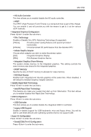
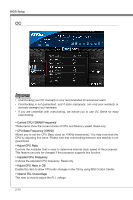
BIOS Setup ▶ tWR Determines minimum time interval between end of write data burst and the start of a pre-charge command. Allows sense amplifiers to restore data to cell. ▶ tWTR Determines minimum time interval between the end of write data burst and the start of a column-read command; allows I/O gating to overdrive sense amplifies before read command starts. ▶ tRRD Specifies the active-to-active delay of different banks. ▶ tRTP Time interval between a read and a precharge command. ▶ tFAW This item is used to set the tFAW (four activate window delay) timing. ▶ tWCL This item is used to set the tWCL (Write CAS Latency) timing. ▶ tCKE This item is used to set the Pulse Width for DRAM module. ▶ tRTL This item is used to set Round Trip Latency settings. ▶ Advanced Channel 1/ 2 Timing Configuration Press to enter the sub-menu. And you can set the advanced memory timing for each channel. ▶ GT OverClocking This item allows you to enable/ disable the overclocking of integrated graphics. ▶ GT Ratio This setting controls the ratio of integrated graphics frequency to enable the integrated graphics to run at different frequency combinations. ▶ Adjusted GT Frequency It shows the iGPU frequency. Read-only. ▶ Spread Spectrum This function reduces the EMI (Electromagnetic Interference) generated by modulating clock generator pulses. Important • If you do not have any EMI problem, leave the setting at [Disabled] for optimal system stability and performance. But if you are plagued by EMI, select the value of Spread Spectrum for EMI reduction. • The greater the Spread Spectrum value is, the greater the EMI is reduced, and the system will become less stable. For the most suitable Spread Spectrum value, please consult your local EMI regulation. • Remember to disable Spread Spectrum if you are overclocking because even a slight jitter can introduce a temporary boost in clock speed which may just cause your over- 2-12
-
 1
1 -
2
-
3
-
4
-
5
-
6
-
7
-
8
-
9
-
10
-
11
-
12
-
13
-
14
-
15
-
16
-
17
-
18
-
19
-
20
-
21
-
22
-
23
-
24
-
25
-
26
-
27
-
28
-
29
-
30
-
31
-
32
-
33
-
34
-
35
-
36
-
37
-
38
-
39
-
40
-
41
-
42
-
43
-
44
-
 45
45 -
 46
46 -
 47
47 -
 48
48 -
 49
49 -
 50
50 -
 51
51 -
 52
52 -
 53
53 -
 54
54 -
 55
55 -
56
-
57
-
58
-
59
-
60
-
61
-
62
-
63
-
64
-
65
-
66
-
67
-
68
-
69
-
70
-
71
-
72
-
73
-
74
-
75
-
76
-
77
-
78
-
79
-
80
 |
 |
