Mackie ART200A Quick Start Guide - Page 2
Rear Panel Features, and Controls, Installation, Connections - art 200a speakers
 |
View all Mackie ART200A manuals
Add to My Manuals
Save this manual to your list of manuals |
Page 2 highlights
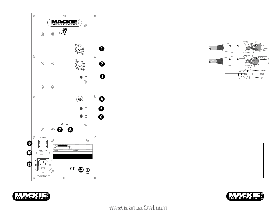
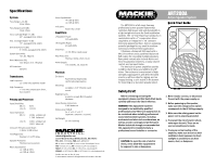
ART 200A ACTIVE SPEAKER SYSTEM INPUT OUTPUT LINE/MIC LINE MIC VOLUME MUSIC OFF ON VOICE OFF ON ON LIMITER CAUTION RISK OF ELECTRIC SHOCK DO NOT OPEN WARNING: TO REDUCE THE RISK OF FIRE OR ELECTRIC SHOCK, DO NOT EXPOSE THIS EQUIPMENT TO RAIN OR MOISTURE. DO NOT REMOVE COVER. NO USER SERVICEABLE PARTS INSIDE. REFER SERVICING TO QUALIFIED PERSONNEL. AVIS: RISQUE DE CHOC ELECTRIQUE - NE PAS OUVRIR REPLACE WITH THE SAME TYPE FUSE AND RATING. DISCONNECT SUPPLY CORD BEFORE CHANGING FUSE UTILISE UN FUSIBLE DE RECHANGE DE MÊME TYPE. DEBRANCHER AVANT DE REMPLACER LE FUSIBLE SERIAL NUMBER MANUFACTURING DATE CONCEIVED, DESIGNED, AND MANUFACTURED BY MACKIE INDUSTRIAL • MADE IN ITALY PATENTS PENDING • COPYRIGHT ©1999 THE FOLLOWING ARE TRADEMARKS /REGISTERED TRADEMARKS OF MACKIE DESIGN INC.: "MACKIE", "MACKIE INDUSTRIAL", & THE "RUNNING MAN" FIGURE THIS APPARATUS MUST BE GROUNDED Rear Panel Features and Controls 1. INPUT is a balanced XLR input jack that accepts mic-level or line-level signals. 2. OUTPUT is a balanced XLR output jack in parallel with the INPUT jack, allowing the signal to "loop through" for daisy-chaining speakers together. Connections The XLR connectors use the following AES standard: Pin 1 = Ground (Shield) Pin 2 = Hot (+) Pin 3 = Cold (-) 3. LINE/MIC switch for mic-level or line-level signals at the INPUT. 4. VOLUME control adjusts the input-stage gain. 5. MUSIC equalization switch ON provides a low-frequency and high-frequency boost. 6. VOICE equalization switch ON provides a gentle boost at 3kHz and 6kHz. 7. ON indicator illuminates when the POWER switch is turned on. Installation 8. LIMITER indicator illuminates when the limiting protection circuits are activated. 9. POWER switch turns the AC power on and off. 10. Voltage Select Switch for setting the AC voltage operation for the voltage being used. 11. IEC AC Socket. Connect the detachable power cord to the socket. The protection fuse is also contained in the AC socket. A 1-3/8" (35mm) socket is provided in the bottom of the cabinet for mounting the loudspeaker on a speaker stand. The ART200A can be suspended with approved rigging hardware. Always use at least two M10 threaded inserts located on opposite sides of the enclosure. The speaker must be positioned so that the weight of the enclosure is equally distributed over the two inserts. CAUTION: Replace fuse only with the same type as indicated on the rear panel. 12. Grounding Terminal provides an additional safety grounding point. WARNING: Never attempt to suspend the ART Series loudspeakers by their handles. Consult a professional rigger or structural engineer prior to suspending loudspeakers from a structure not intended for that use. Always know the working load limit of the structure supporting the loudspeaker array. Always make sure that the rigging hardware minimum rating is at least five times the actual load.
-
 1
1 -
 2
2
 |
 |