Mackie Onyx 32.4-Bus Owner's Manual - Page 15
Matrix, Compressor, and Metering THRESHOLD, ²7. RATIO - 32 channel mixer
 |
View all Mackie Onyx 32.4-Bus manuals
Add to My Manuals
Save this manual to your list of manuals |
Page 15 highlights
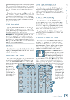
Owner's Manual Matrix, Compressor, and Metering Section 32. MATRIX A and B Input Controls The Matrix A and B controls allow you to create separate mixes, or a stereo mix, from Groups 1 through 4 and the Left and Right Mix outputs. Simply adjust the six matrix input controls to create the mix you want at the MATRIX A or B outputs. tantly, auto-gain compensation that provides the appropriate amount of makeup gain based on the amount of compression taking place. The following knobs and switches are used to control the compressor. 36. THRESHOLD 33. MATRIX A and B MASTER Controls Use these controls to adjust the overall signal level at the MATRIX A and B outputs. Determines the level at which the compressor begins to act on the incoming signal. It is calibrated in decibels, ranging from -30 to +10 dB. 34. AFL Solo Switch The AFL switch allows you to hear the Matrix signal through your headphones or monitor outputs. This comes after the MATRIX MASTER, so you can hear the relative signal level of each Matrix output. When you engage the AFL switch on both MATRIX A and B, the soloed signal appears in stereo in the headphones and monitor outputs. This is useful when you want to use both Matrix outputs to create a stereo mix. Remember, PFL solo mode always overrides AFL solo mode. If you engage a PFL solo switch on a mono or stereo channel, the AFL solo is disconnected from the headphones and monitor outputs and replaced with the PFL signal. The Rude Solo LEDS below the SOLO meters indicate which solo mode is active. 35. COMPRESSOR/LIMITER A compressor is used to reduce or limit transient peaks in a signal. As the input level to the compressor increases, the output level from the compressor increases linearly until the threshold point is reached. After that point, the output level no longer increases linearly. Instead, it increases at a reduced rate determined by the ratio setting. In other words, the greater the ratio setting, the less the output level changes as a function of the input level. A compressor is often used on an individual signal (voice) or group of signals (drums) to smooth out transients and allow signals to sit in the mix without harshly cutting through. A limiter, on the other hand, is often used between the mixer and the amplifier(s) to avoid power amplifier clipping or overdriving the speakers, known as system limiting. The Onyx 4•Bus design team decided the compressor/limiter functions could be carried out onboard using a new integrated analog stereo compressor/limiter chip designed by THAT Corporation. It provides threshold, ratio, fast/slow attack control and, perhaps most impor- 37. RATIO Determines the change in output level as a function of the change in input level, once the threshold has been exceeded. The Ratio control ranges from OFF (1:1) to LIMIT (∞:1). Thus, if the ratio is 2:1, an increase in input level of 10 dB (assuming the input is above the threshold level) results in a 5 dB increase in output level. When set to LIMIT, the compressor acts as a peak limiter. After the initial attack time, the output changes very little once the input crosses the threshold. OO OO OO OO OO OO OO OO OO OO OO OO OO OO PREMIUM ANALOG MIXER w/ PERKINS EQ MATRIX A B GRP 1 -10 -20 0 MAX GRP 2 MAX MAX -30 +10 THRESHOLD 2:1 MAX 1.5:1 5:1 GRP 3 MAX GRP 4 MAX MAX OFF LIMIT RATIO MAIN GRP MIX 1-2 OFF GRP 3-4 MAX COMP ASSIGN MAX MAX LEFT MAX MAX RIGHT FAST ATTACK POWER LAMP 12V, 0.5A PHONES COMPRESSOR INPUT G.R. 0dB=0dBu 20 CLIP 1 15 2 10 3 6 4 3 5 0 6 2 7 4 8 7 9 10 10 20 12 30 15 MAIN MIX LEFT RIGHT CLIP 0dB=0dBu 20 15 10 6 3 LEVEL SET 0 2 4 7 10 20 30 BYPASS COMP PFL AFL RUDE SOLO +15 +15 MASTER STEREO AFL AFL OO MAX PHONES MAX MAX OO OO MONITOR SOLO LEVEL TB ASSIGN OO MAX MONO MAIN MAIN AUX AUX AUX OO MAX TO MON MIX 1-2 3-4 5-6 TALKBACK Owner's Manual 15
-
 1
1 -
2
-
3
-
4
-
5
-
6
-
7
-
8
-
9
-
 10
10 -
 11
11 -
 12
12 -
 13
13 -
 14
14 -
 15
15 -
 16
16 -
 17
17 -
 18
18 -
 19
19 -
 20
20 -
21
-
22
-
23
-
24
-
25
-
26
-
27
-
28
-
29
-
30
-
31
-
32
-
33
-
34
-
35
-
36
 |
 |
