Magic Chef MCO160UWF User Manual - Page 5
A-2. Install the Mounting Plate, Step. 1 Setup position, Step. 2 Drilling, Step. 3 Tightening
 |
View all Magic Chef MCO160UWF manuals
Add to My Manuals
Save this manual to your list of manuals |
Page 5 highlights
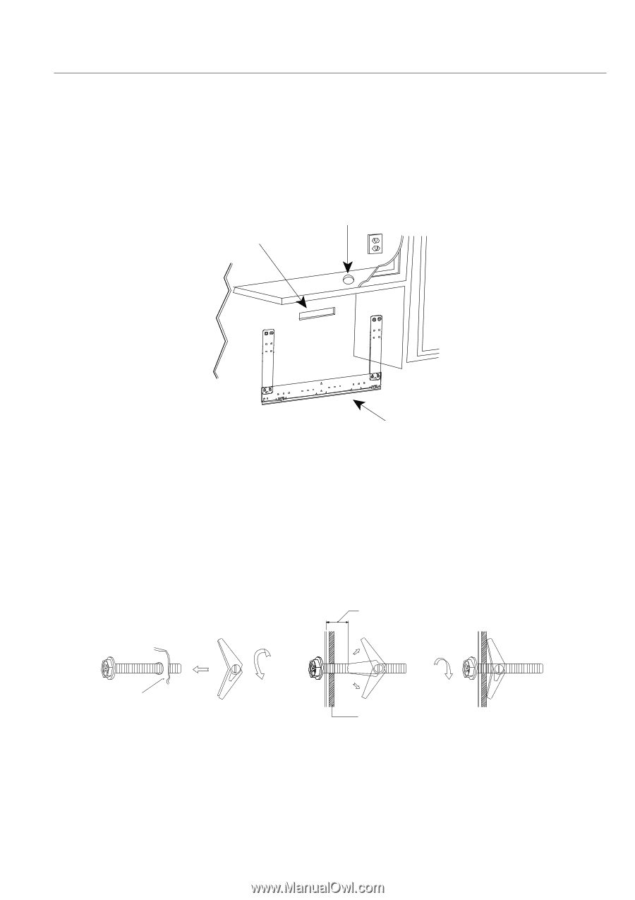
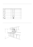
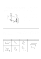
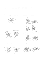
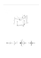
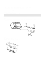
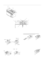
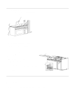
A-2. Install the Mounting Plate Step. 1 Setup position a. Draw a line down the middle of the studs(See the Wall Construction, page 3) b. Draw a vertical line on the wall at the center of the 30" wide space. NOTE: Use the wall template for the rear wall. Reference Wall Template prior to proceeding. Installation of this product require 2 persons. Step. 2 Drilling Reference the Wall Template. Power Supply Cord Hole House Duct Mounting Plate Step. 3 Tightening the screws To Attach the mounting plate to the wall using the toggle bolt assemblies and/or lag screws: a. Insert toggle bolts through mounting plate at required locations and add the spring loaded toggles. Be sure you leave space at least the thickness of the wall between the mounting plate and the end of the toggle nut, (in closed position). If you do not leave this space, the toggle nut will not open on the other side of the wall. b. Position mounting plate on wall and insert toggle bolt assemblies through the drywall holes or start the lag-screw(s) through the wall stud(s). c. Next, secure mounting plate to the wall by tightening toggle bolt assemblies or lag screw(s). Space more than wall thickness Mounting plate Dry Wall d. Drill 3/16" diameter lag screw hole(s), into one or more wall studs. (Remember, you must have at least one lag screw into a wall stud.)For stud location refer to WALL CONSTRUCTION see page 3 e. Tighten the lag screw(S) into wall stud(S) 5
-
 1
1 -
 2
2 -
 3
3 -
 4
4 -
 5
5 -
 6
6 -
 7
7 -
 8
8 -
 9
9 -
 10
10 -
 11
11 -
12
-
13
-
14
-
15
-
16
 |
 |