Magic Chef MCSCTG24S User Guide - Page 14
Electrical Connection
 |
View all Magic Chef MCSCTG24S manuals
Add to My Manuals
Save this manual to your list of manuals |
Page 14 highlights
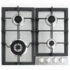
Electrical Connection WARNING: Electrical Shock Hazard • Always disconnect the electrical plug from the wall receptacle before servicing this unit. • Plug into a grounded 3 prong outlet. • Do not remove the ground prong from the power cord plug. • Do not use an adapter. • Do not use an extension cord. • Failure to do so can result in death, fire or electrical shock. NOTE: Before making the connection, make sure of the following. • The safety circuit breaker and the electrical system are able to withstand the load of the appliance. • The power supply system has a ground connection in good working order in accordance with the regulation. • The electrical socket should be easily accessible with the appliance installed. In all cases, the power supply lead must be positioned so that it does not reach a temperature of 122°F above the room temperature at any point. WARNING: Severe shock or damage to the cooktop may occur if the cooktop is not installed by a qualified service technician. WARNING: If for any reason a gas control knob is turned ON and there is no electric power to operate the electronic igniter of the cooktop, turn off all gas control knobs and wait 5 minutes for gas to dissipate before lighting the burner manually. WARNING: To light the burner manually, carefully hold a lighted match to the burner ports and push and turn the gas control knob to HI until it lights and then turn the knob to the desired setting. Copper or Stainless Steel Pipe Figure 17 Clamps Rear View Clamps Rear View Properly Connected Not Properly Connected Assembling the Burners The electrode of the electronic ignition system is positioned above the surface of the burner base. Do not remove a burner cap or touch the electrode of a burner while another is turned on. Damage or electrical shock may occur. 1. Place burner heads over the burner base. Make sure the hole in the burner head is properly aligned with the electrode in the burner base. (Refer to Figure 18.) 14
-
 1
1 -
2
-
3
-
4
-
5
-
6
-
7
-
8
-
 9
9 -
 10
10 -
 11
11 -
 12
12 -
 13
13 -
 14
14 -
 15
15 -
 16
16 -
 17
17 -
 18
18 -
 19
19 -
20
-
21
-
22
-
23
-
24
-
25
-
26
-
27
-
28
-
29
-
30
-
31
-
32
-
33
-
34
-
35
-
36
-
37
-
38
-
39
-
40
-
41
-
42
-
43
-
44
 |
 |
