Magnavox 27MS343S User manual, English (US) - Page 7
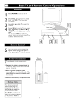
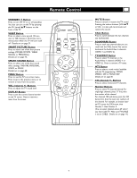
Basic TV to VCR Accessory Connection - remote control
 |
View all Magnavox 27MS343S manuals
Add to My Manuals
Save this manual to your list of manuals |
Page 7 highlights
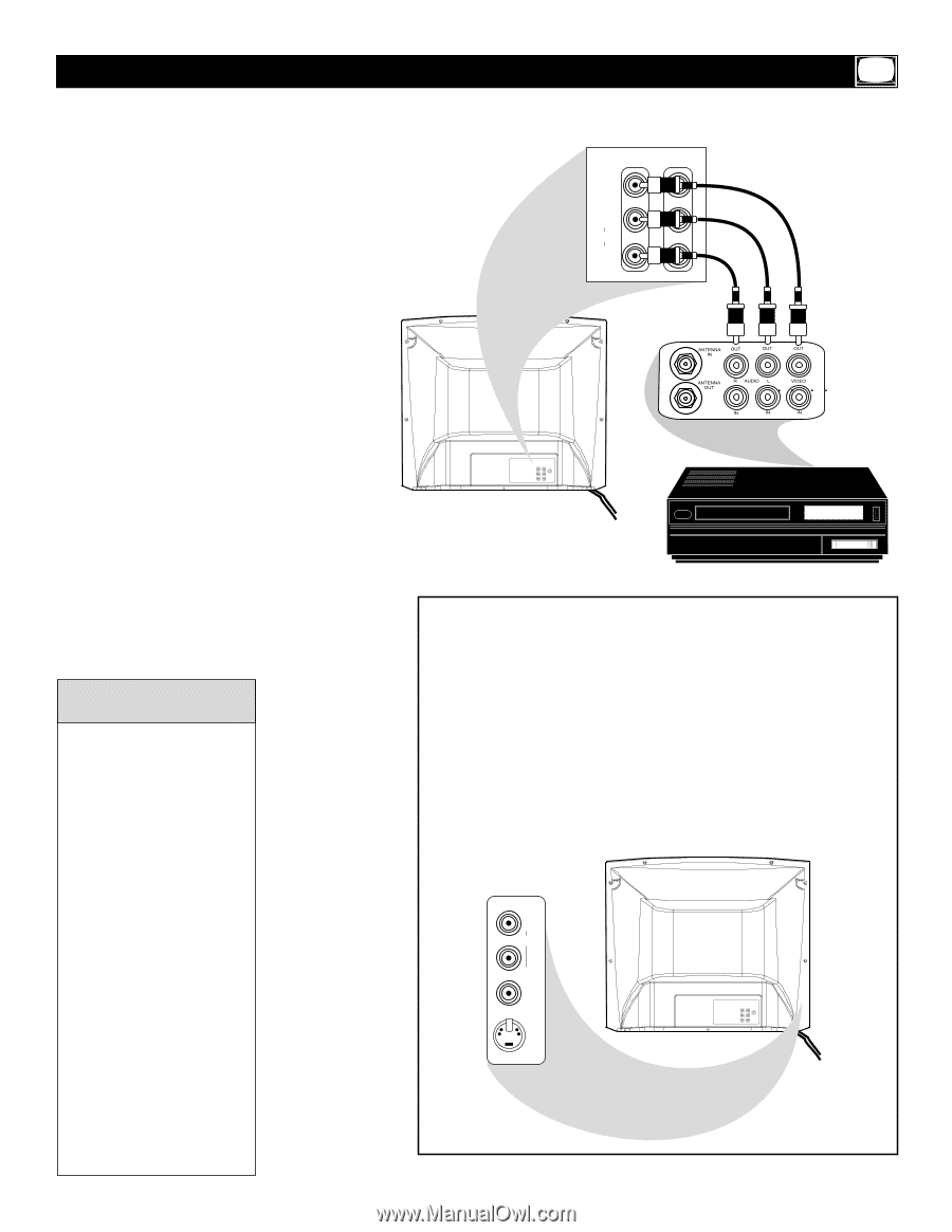
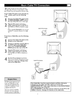
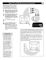
Basic TV to VCR (Accessory) Connection T he basic Antenna/Cable TV to Accessory (VCR, DVD Player, etc.) to TV connection is shown at right. For other hookups (such as those with Cable Boxes), refer to the owner's manual of the Cable Box or other Accessories. 1 Connect a yellow video cable to the VIDEO IN 2 jack on the rear of the TV and to the VIDEO OUT jack on your VCR (or other accessory). 2 Connect red and white audio cables to the AUDIO IN 2 jacks (left and right) on the rear of the TV and to the AUDIO OUT jacks on the VCR (or other device). Match the cable colors to the jack colors. 3 Turn on the TV and the VCR. IN 2 VIDEO OUTPUT L(MONO) L AUDIO R R 4 Press theTV/AV/EXIT button on the TV's remote control until VIDEO 2 appears in the upper right corner of the TV screen.When you play material on the VCR, DVD Player, etc. that is connected to the AUDIO and VIDEO IN 2 jacks on the rear of the TV, it will appear on the TV on the VIDEO 2 channel. Helpful Hints Audio and video cables are not supplied with the TV. Audio cables are usually marked with red and white. Video cables (CVBS) are usually marked with yellow. You can connect the antenna or Cable TV signal to either the ANTENNA IN jack on your VCR or to the 75 OHM ANTENNA INPUT jack on the TV. If you connect it to the VCR, choose TV channels at the VCR. Connect it to the VCR if you want to record TV programming through the VCR. Your VCR may not have Audio and Video Out jacks, but only an RF or ANTENNA OUT jack. Use an RF coaxial cable to connect the VCR's ANTENNA OUT jack to the TV's 75 OHM ANTENNA INPUT jack. IN 2 VIDEO OUTPUT 75 OHM ANTENNA INPUT L(MONO) L AUDIO R R There are more AUDIO and VIDEO IN jacks at the lower-right corner of the rear of the TV. These are the AUDIO and VIDEO IN 1 jacks. Use these if you have more equipment to connect to the TV. To view material playing on equipment connected to these jacks, select the VIDEO 1 channel at the TV. (Press TV/AV/EXIT so VIDEO 1 appears in the top right corner of the TV screen.) There is also an S-VIDEO IN jack in this area. Use S-Video connections instead if your DVD Player, Camcorder, etc., has an S-Video Out jack. S-Video provides a clearer picture than the standard CVBS video (the yellow jack). Choose the VIDEO 1 channel to view material playing on equipment connected to the S-VIDEO IN jack. Use either the S-VIDEO IN 1 jack or the VIDEO IN 1 jack.You cannot use both at the same time for the same piece of equipment. Doing so would interfere with the picture display. IN1 R AUDIO L (MONO) VIDEO S-VIDEO IN 2 VIDEO OUTPUT 75 OHM ANTENNA INPUT L(MONO) L AUDIO R R 7
-
 1
1 -
 2
2 -
 3
3 -
 4
4 -
 5
5 -
 6
6 -
 7
7 -
 8
8 -
 9
9 -
 10
10 -
 11
11 -
 12
12 -
13
-
14
-
15
-
16
-
17
-
18
-
19
-
20
-
21
-
22
-
23
-
24
-
25
-
26
-
27
-
28
-
29
-
30
-
31
-
32
-
33
-
34
-
35
-
36
 |
 |