Magnavox 32MD359B User Manual - Page 9
Rear Panel, Control Panel - remote
 |
UPC - 609585163997
View all Magnavox 32MD359B manuals
Add to My Manuals
Save this manual to your list of manuals |
Page 9 highlights
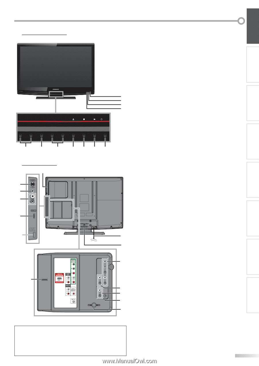
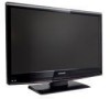
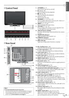
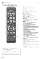
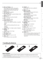
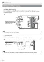
5 Control Panel - VOLUME + MENU - CHANNEL + 8 9 10 11 POWER 7 6 5 5 Rear Panel 12 13 14 15 4321 16 * 17 18 19 24 20 21 22 23 Note: * service terminal (service use only) Use this terminal only when a software update is necessary. Do not connect any device to this terminal such as; digital camera, keyboard, mouse, etc. For more information, please visit at www.magnavox.com/support 1. yPOWER (p. 17) Press to turn the unit on and off. 2. B (play) (p. 38) Press to begin the disc playback. 3. C (stop) (p. 38) Press to stop the disc playback. 4. A (eject) (p. 38) Press to eject the disc. 5. CHANNEL + / - (p. 18 / p. 19) Press to select channels or move up (+) / down (-) through the main menu items. 6. MENU (p. 17 / p. 46) Press to display the main menu. 7. VOLUME + / - (p. 18) Press to adjust the volume or move right (+) / left (-) through the main menu items. 8. infrared sensor window Receives infrared rays transmitted from the remote control. 9. POWER ON indicator Lights up green when power is on. 10. STAND BY indicator Lights up red when power is off. 11. DVD indicator Lights up orange when the disc is inserted. 12. disc loading slot (p. 38) Insert the disc with the label side facing forward. 13. S-video input jack (p. 14) S-video cable connection for an external device. 14. video input jack (p. 15) RCA video cable connection for an external device. 15. audio input jack (p. 14 / p. 15) RCA audio cable connection for an external device. 16. HDMI 2 input jack (p. 12 / p. 13) HDMI connection for HDMI device. 17. AC power cord (p. 16) Connect to a standard AC outlet to supply power to this unit. 18. cable management (p. 16) Use this holder to bundle the cables. 19. component video and audio input jack (p. 12 / p. 14) RCA component video cable and RCA audio cable connection for an external device. 20. audio output jack (p. 15) RCA audio cable connection for an external device. 21. audio input jack for HDMI 1 (p. 13 / p. 16) RCA audio cable connection for a DVI device. When you connect your PC that has a DVI terminal, use a stereo mini plug-RCA conversion cable as well. (For HDMI 1 input jack only) 22. digital audio output jack (p. 15) Coaxial digital cable connection for a decoder or an audio receiver. 23. antenna input jack (p. 12) RF coaxial cable connection for your antenna or cable TV signal. 24. HDMI 1 input jack (p. 12 / p. 13 / p. 16) HDMI connection for HDMI or DVI device. When you connect your PC that has a DVI terminal, you can enjoy this unit as a PC monitor. 9 EN INTRODUCTION PREPARATION WATCHING TV OPTIONAL SETTING OPERATING DVD DVD SETTING TROUBLESHOOTING INFORMATION
-
 1
1 -
2
-
3
-
 4
4 -
 5
5 -
 6
6 -
 7
7 -
 8
8 -
 9
9 -
 10
10 -
 11
11 -
 12
12 -
 13
13 -
 14
14 -
15
-
16
-
17
-
18
-
19
-
20
-
21
-
22
-
23
-
24
-
25
-
26
-
27
-
28
-
29
-
30
-
31
-
32
-
33
-
34
-
35
-
36
-
37
-
38
-
39
-
40
-
41
-
42
-
43
-
44
-
45
-
46
-
47
-
48
-
49
-
50
-
51
-
52
-
53
-
54
-
55
-
56
 |
 |