Magnavox 32MF339B User Manual - Page 7
Control Panel, Terminals - video settings
 |
UPC - 609585163980
View all Magnavox 32MF339B manuals
Add to My Manuals
Save this manual to your list of manuals |
Page 7 highlights
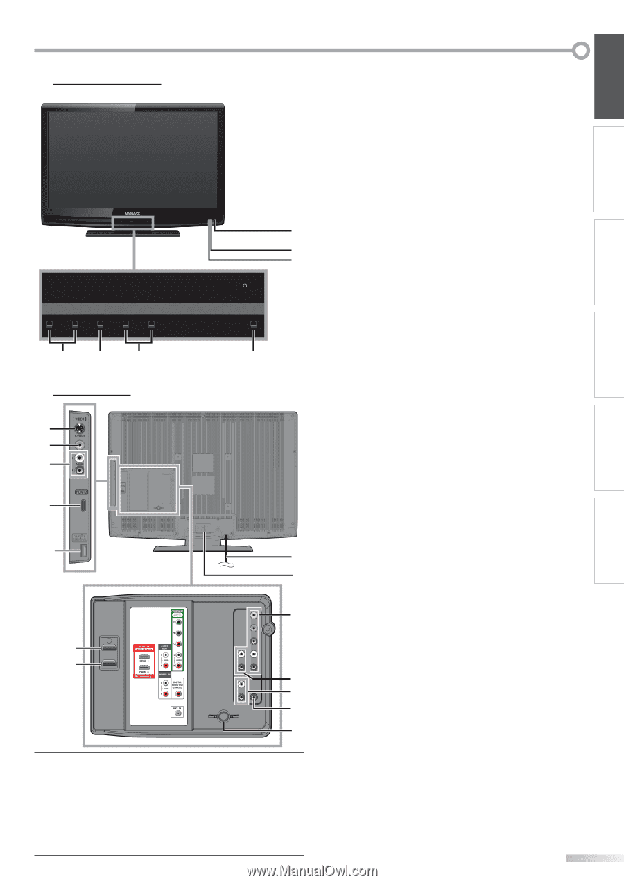
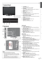
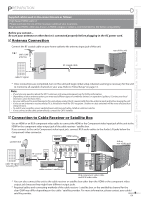
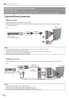
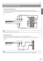
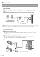
INTRODUCTION PREPARATION WATCHING TV OPTIONAL SETTING TROUBLESHOOTING INFORMATION Control Panel - VOLUME + MENU - CHANNEL + 1. yPOWER (p. 14) Press to turn the unit on and off. 2. CHANNEL + / - (p. 15 / p. 16) Press to select channels or move up (+) / down (-) through the main menu items. 3. MENU (p. 19) Press to display the main menu. 4. VOLUME + / - (p. 15) Press to adjust the volume or move right (+) / left (-) through the main menu items. 5 5. Infrared sensor window 6 7 Receives infrared rays transmitted from the remote control. 6. POWER ON indicator Lights up green when power is on. POWER 7. STAND BY indicator Lights up red when power is off. 4 3 2 1 Terminals 8 9 10 11 * 12 13 14 19 20 15 16 17 18 Note: * service terminal (service use only) • Use this terminal only when a software update is necessary. • User should not connect any devices to the service terminal such as digital camera, keyboard, mouse, etc. (because these will not work). • The software update is, in most cases, handled by an authorized service person or in some circumstances the user may be asked to do the software upgrade themselves. [Side Panel] 8. S-Video Input jack (p. 11) S-Video cable connection from an external device. 9. Video Input jack (p. 12) RCA video cable connection from an external device. 10. Audio Input jack (p. 11 / p. 12) RCA audio cable connection from an external device. 11. HDMI 2 Input jack (p. 9 / p. 10) HDMI connection from HDMI device. [Rear Panel] 12. AC power cord (p. 13) Connect to a standard AC outlet to supply power to this unit. 13. Cable management (p. 13) Use this holder to bundle the cables. 14. Component video and Audio Input jack (p. 9 / p. 11) RCA component video cable and RCA audio cable connection from an external device. 15. Audio Output jack (p. 12) RCA audio cable connection for an external device. 16. Audio Input jack for HDMI1 (p. 10 / p. 13) RCA audio cable connection from a DVI device. When you connect your PC that has a DVI terminal, use a stereo mini plug-RCA conversion cable as well. (For HDMI 1 Input jack only) 17. Digital audio Output jack (p. 12) Coaxial digital cable connection for a decoder or an audio receiver. 18. Antenna Input jack (p. 9) RF coaxial cable connection for your antenna or cable TV signal. 19. HDMI 1 Input jack (p. 9 / p. 10 / p. 13) HDMI connection for HDMI or DVI device. When you connect your PC that has a DVI terminal, you can enjoy this unit as a PC monitor. 20. HDMI 3 Input jack (p. 9 / p. 10) HDMI connection from HDMI device. 7 EN
-
 1
1 -
 2
2 -
 3
3 -
 4
4 -
 5
5 -
 6
6 -
 7
7 -
 8
8 -
 9
9 -
 10
10 -
 11
11 -
 12
12 -
13
-
14
-
15
-
16
-
17
-
18
-
19
-
20
-
21
-
22
-
23
-
24
-
25
-
26
-
27
-
28
-
29
-
30
-
31
-
32
-
33
-
34
-
35
-
36
-
37
-
38
-
39
 |
 |