Makita 4114 Owners Manual - Page 5
Assembly, Operation
 |
View all Makita 4114 manuals
Add to My Manuals
Save this manual to your list of manuals |
Page 5 highlights
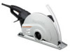
Switch action A B 1 2 004015 1. Switch trigger 2. Lock lever 3 5 4 004378 1. Flange 2. Ring 3. Wheel 4. Flange 5. Hex bolt 1 2 CAUTION: • Before plugging in the tool, always check to see that the switch trigger actuates properly and returns to the "OFF" position when released. • Switch can be locked in "ON" position for ease of operator comfort during extended use. Apply caution when locking tool in "ON" position and maintain firm grasp on tool. To start the tool, simply pull the switch trigger. (A direction) Release the switch trigger to stop. For continuous operation, pull the switch trigger (A direction) and then push in the lock lever.(B direction) To stop the tool from the locked position, pull the switch trigger (A direction) fully, then release it. ASSEMBLY CAUTION: • Always be sure that the tool is switched off and unplugged before carrying out any work on the tool. Installing or removing the wheel 004016 1. Shaft lock 2. Socket wrench CAUTION: • Use only the Makita wrench to install or remove the wheel. OPERATION CAUTION: Be sure to pull the tool when cutting a workpiece. • Use this tool for straight line cutting only. Cutting curves can cause stress cracks or fragmentation of the diamond wheel and abrasive cut-off wheel resulting in possible injury to persons in the vicinity. • After operation, always switch off the tool and wait until the wheel has come to a complete stop before putting the tool down. • When cutting concrete blocks, tiles or masonry materials, do not make a cut in depth more than 60 mm (2-3/8"). When you need to cut a workpiece over 60 mm (2-3/8") up to 100 mm (4"), make more than two passes of cuts. The depth of the most efficient cut is about 40 mm (1-9/16"). Hold the tool firmly with both hands. First keep the wheel without making any contact with a workpiece to be cut. Then turn the tool on and wait until the wheel attains full speed. 004380 2 1. Notch 2. Cutting line 2 1 To remove the wheel, depress the shaft lock to hold the shaft stationary, then loosen the hex bolt clockwise with the socket wrench. To install a wheel, place flange with its partly elevated side facing the tool, and then place ring before installing a wheel onto the spindle (shaft) and another flange with partly elevated side facing outward. Be sure to fully tighten the hex bolt counterclockwise after mounting the new wheel, or operation will be dangerous. 1 The cut is made by pulling the tool toward you (not by pushing away from you). Align the notch on the base with your cutting line when performing a cut. Switch off the tool on the position posed when finishing a cut. Raise the tool after the wheel comes to a complete stop. 5
-
 1
1 -
 2
2 -
 3
3 -
 4
4 -
 5
5 -
 6
6 -
 7
7 -
 8
8 -
 9
9 -
 10
10 -
 11
11 -
12
-
13
-
14
-
15
-
16
-
17
-
18
-
19
-
20
-
21
-
22
-
23
-
24
 |
 |
