Makita 9566PC Owners Manual - Page 8
Assembly
 |
View all Makita 9566PC manuals
Add to My Manuals
Save this manual to your list of manuals |
Page 8 highlights
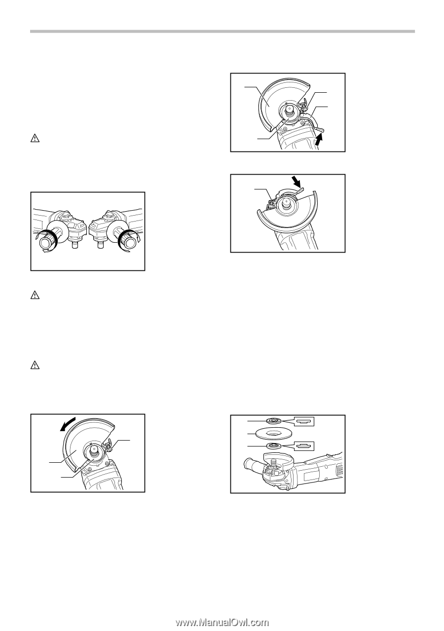
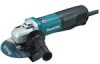
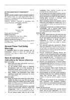
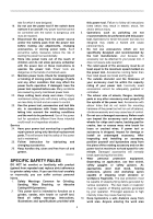
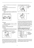
returns to admissible levels, the tool will operate as normal. Soft start feature • Soft start because of suppressed starting shock. ASSEMBLY For tool with clamp lever type wheel guard 1. Wheel guard 1 2. Bearing box 3 3. Screw 4 4. Lever CAUTION: • Always be sure that the tool is switched off and unplugged before carrying out any work on the tool. Installing side grip (handle) 2 008375 1 1. Screw 008376 008373 CAUTION: • Always be sure that the side grip is installed securely before operation. Screw the side grip securely on the position of the tool as shown in the figure. Installing or removing wheel guard CAUTION: • The wheel guard must be fitted on the tool so that the closed side of the guard always points toward the operator. For tool with locking screw type wheel guard 1. Wheel guard 2. Bearing box 3. Screw 3 1 2 Pull the lever in the direction of the arrow after loosening the screw. Mount the wheel guard with the protrusion on the wheel guard band aligned with the notch on the bearing box. Then rotate the wheel guard around 180°. Fasten it with the screw after pulling lever in the direction of the arrow for the working purpose. The setting angle of the wheel guard can be adjusted with the lever. To remove wheel guard, follow the installation procedure in reverse. Installing or removing depressed center grinding wheel/Multi-disc (accessory) Mount the inner flange onto the spindle. Fit the wheel/disc on the inner flange and screw the lock nut onto the spindle. 1 1. Lock nut 2. Depressed 2 center grinding 3 wheel/Multi-disc 3. Inner flange 008374 008377 Mount the wheel guard with the protrusion on the wheel guard band aligned with the notch on the bearing box. Then rotate the wheel guard around 180 degrees counterclockwise. Be sure to tighten the screw securely. To remove wheel guard, follow the installation procedure in reverse. To tighten the lock nut, press the shaft lock firmly so that the spindle cannot revolve, then use the lock nut wrench and securely tighten clockwise.To remove the wheel, follow the installation procedure in reverse. 8
-
 1
1 -
2
-
 3
3 -
 4
4 -
 5
5 -
 6
6 -
 7
7 -
 8
8 -
 9
9 -
 10
10 -
 11
11 -
 12
12
 |
 |