Makita 9820-2 Owners Manual - Page 4
All Grounded, Cord-connected Tools - used
 |
View all Makita 9820-2 manuals
Add to My Manuals
Save this manual to your list of manuals |
Page 4 highlights
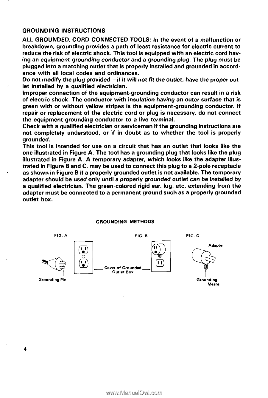
GROUNDING INSTRUCTIONS ALL GROUNDED, CORD-CONNECTED TOOLS: In the event of a malfunction or breakdown, grounding provides a path of least resistance for electric current t o reduce the risk of electric shock. This tool is equipped with an electric cord hav- ing an equipment-grounding conductor and a grounding plug. The plug must be plugged into a matching outlet that is properly installed and grounded in accord- ance with all local codes and ordinances. . Do not modify the plug provided -if it will not fit the outlet, have the proper out- let installed by a qualified electrician. Improper connection of the equipment-grounding conductor can result in a risk of electric shock. The conductor with insulation having an outer surface that is green with or without yellow stripes is the equipment-grounding conductor. If repair or replacement of the electric cord or plug is necessary, do not connect the equipment-grounding conductor to a live terminal. Check with a qualified electrician or serviceman if the grounding instructions are not completely understood, or if in doubt as t o whether the tool is properly grounded. This tool is intended for use on a circuit that has an outlet that looks like the one illustrated in Figure A. The tool has a grounding plug that looks like the plug illustrated in Figure A. A temporary adapter, which looks like the adapter illus- . trated in Figure B and C, may be used t o connect this plug t o a 2-pole receptacle as shown in Figure B if a properly grounded outlet is not available. The temporary adapter should be used only untila properly grounded outlet can be installed by a qualified electrician. The green-colored rigid ear, lug, etc. extending from the adapter must be connected t o a permanent ground such as a properly grounded outlet box. FIG. A Q I Grounding Pin GROUNDING METHODS FIG. B - -Cover of Grounded Outlet Box FIG. C Adapter Grounding Means 4
-
 1
1 -
 2
2 -
 3
3 -
 4
4 -
 5
5 -
 6
6 -
 7
7 -
 8
8 -
 9
9 -
 10
10 -
11
-
12
-
13
-
14
-
15
-
16
 |
 |