Makita GV7000C Owners Manual - Page 6
Functional, Description
 |
View all Makita GV7000C manuals
Add to My Manuals
Save this manual to your list of manuals |
Page 6 highlights
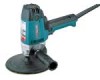
FUNCTIONAL DESCRIPTION CAUTION: • Always be sure that the tool is switched off and unplugged before adjusting or checking function on the tool. 1 2 1. Switch trigger 2. Lock button 003407 Switch action CAUTION: • Before plugging in the tool, always check to see that the switch trigger actuates properly and returns to the "OFF" position when released. • Switch can be locked in "ON" position for ease of operator comfort during extended use. Apply caution when locking tool in "ON" position and maintain firm grasp on tool. To start the tool, simply pull the switch trigger. Release the switch trigger to stop. For continuous operation, pull the switch trigger and then push in the lock button. To stop the tool from the locked position, pull the switch trigger fully, then release it. 003408 Speed adjusting dial 2 1 The tool speed can be changed by turning the speed adjusting dial to a given number setting from 1 to 5. Higher speed is obtained when the dial is turned in the direction of number 5. And lower speed is obtained when it is turned in the direction of number 1. 1. Speed adjusting dial Number 1 | 2 | 3 | 4 | 5 003409 RPM (/min) 2,500 | 2,800 | 3,500 | 4,200 | 4,700 Refer to the table for the relationship between the number settings on the dial and the approximate tool speed. CAUTION: • If the tool is operated continuously at low speeds for a long time, the motor will get overloaded, resulting in tool malfunction. • The speed adjusting dial can be turned only as far as 5 and back to 1. Do not force it past 5 or 1, or the speed adjusting function may no longer work. 6
-
 1
1 -
 2
2 -
 3
3 -
 4
4 -
 5
5 -
 6
6 -
 7
7 -
 8
8 -
 9
9 -
 10
10 -
 11
11 -
 12
12 -
13
-
14
-
15
-
16
 |
 |
