Makita HP2010N Owners Manual - Page 6
Functional, Description
 |
View all Makita HP2010N manuals
Add to My Manuals
Save this manual to your list of manuals |
Page 6 highlights
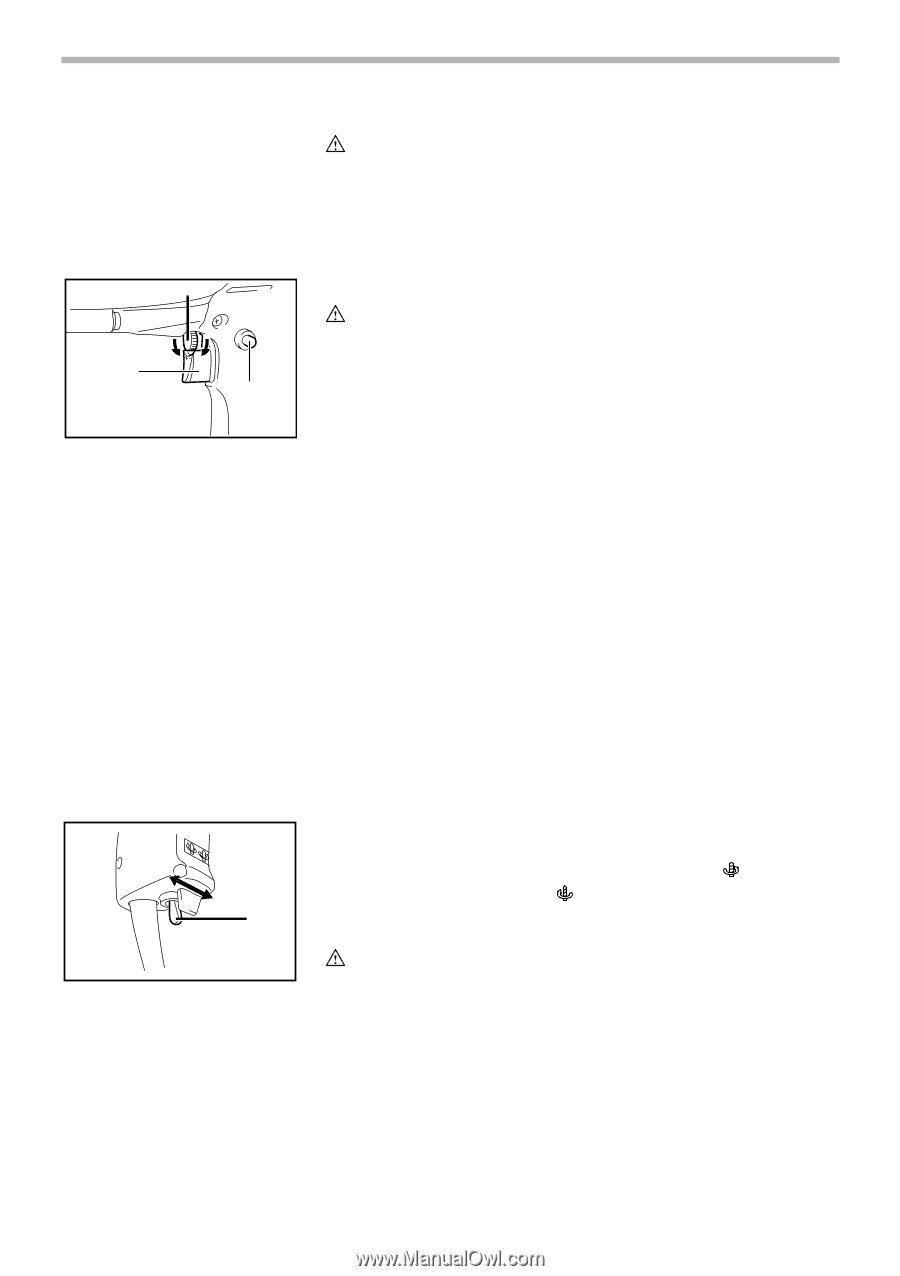
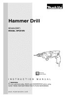
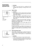
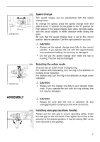
FUNCTIONAL DESCRIPTION CAUTION: • Always be sure that the tool is switched off and unplugged before adjusting or checking function on the tool. 1 23 4 1. Speed control screw 2. Low 3. High 4. Switch trigger 5. Lock button 002457 5 Switch action CAUTION: • Before plugging in the tool, always check to see that the switch trigger actuates properly and returns to the "OFF" position when released. • Switch can be locked in "ON" position for ease of operator comfort during extended use. Apply caution when locking tool in "ON" position and maintain firm grasp on tool. To start the tool, simply pull the switch trigger. Tool speed is increased by increasing pressure on the switch trigger. Release the switch trigger to stop. For continuous operation, pull the switch trigger and then push in the lock button. To stop the tool from the locked position, pull the switch trigger fully, then release it. A speed control screw is provided so that maximum tool speed can be limited (variable). Turn the speed control screw clockwise for higher speed, and counterclockwise for lower speed. 002411 1 Reversing switch action This tool has a reversing switch to change the direction of rotation. Move the reversing switch lever to the position for clockwise rotation or the position for counterclockwise rotation. 1. Reversing switch lever CAUTION: • Always check the direction of rotation before operation. • Use the reversing switch only after the tool comes to a complete stop. Changing the direction of rotation before the tool stops may damage the tool. 6
-
 1
1 -
 2
2 -
 3
3 -
 4
4 -
 5
5 -
 6
6 -
 7
7 -
 8
8 -
 9
9 -
 10
10 -
 11
11 -
 12
12 -
13
-
14
-
15
-
16
 |
 |