Makita HR5210C Owners Manual - Page 8
Maintenance
 |
View all Makita HR5210C manuals
Add to My Manuals
Save this manual to your list of manuals |
Page 8 highlights
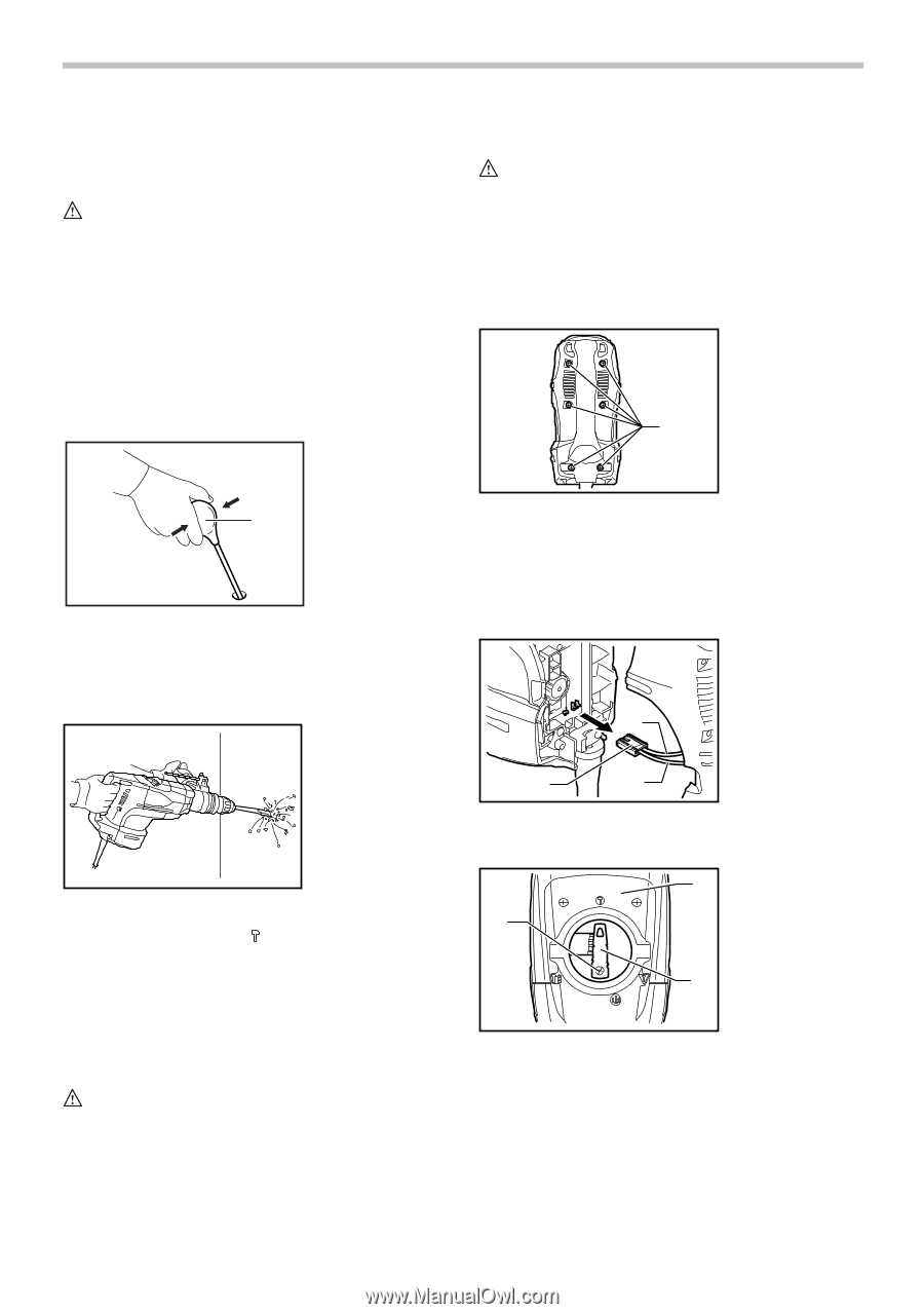
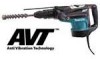
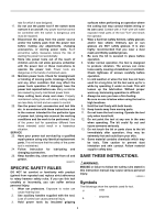
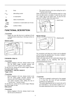
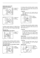
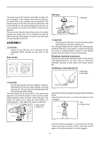
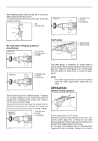
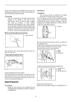
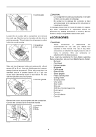
an idle, then remove the bit partially from the hole. By repeating this several times, the hole will be cleaned out and normal drilling may be resumed. CAUTION: • There is a tremendous and sudden twisting force exerted on the tool/bit at the time of hole break-through, when the hole becomes clogged with chips and particles, or when striking reinforcing rods embedded in the concrete. Always use the side grip (auxiliary handle) and firmly hold the tool by both side grip and switch handle during operations. Failure to do so may result in the loss of control of the tool and potentially severe injury. Blow-out bulb (optional accessory) 1. Blow-out bulb Lubrication CAUTION: • This servicing should be performed by Makita Authorized or Factory Service Centers only. This tool requires no hourly or daily lubrication because it has a grease-packed lubrication system. It should be relubricated after every 6 months of operation. Send the complete tool to Makita Authorized or Factory Service Center for this lubrication service. 1. Screws 1 1 002449 After drilling the hole, use the blow-out bulb to clean the dust out of the hole. Chipping/Scaling/Demolition 007851 Run the tool for several minutes to warm it up. Switch off and unplug the tool. Loosen the six screws and remove the handle. Note that the top screws are different from other screws. Disconnect the connector by pulling them. 1. Black 2. White 3. Connector 1 3 2 007852 007850 Set the change lever to the symbol. Hold the tool firmly with both hands. Turn the tool on and apply slight pressure on the tool so that the tool will not bounce around, uncontrolled. Pressing very hard on the tool will not increase the efficiency. MAINTENANCE CAUTION: • Always be sure that the tool is switched off and unplugged before attempting to perform inspection or maintenance. Loosen the screws and remove the change lever. 3 1. Change lever 2. Screw 2 3. Crank cap cover 1 007901 Remove the crank cap cover. Remove the control plate. (Except for model HR5211C.) 8
-
 1
1 -
2
-
 3
3 -
 4
4 -
 5
5 -
 6
6 -
 7
7 -
 8
8 -
 9
9 -
 10
10 -
 11
11 -
 12
12 -
 13
13 -
14
-
15
-
16
-
17
-
18
-
19
-
20
-
21
-
22
-
23
-
24
-
25
-
26
-
27
-
28
-
29
-
30
-
31
-
32
 |
 |