Makita LXPH03 Owners Manual - Page 6
Reversing switch action, Speed change, Selecting the action mode, Adjusting the fastening torque
 |
View all Makita LXPH03 manuals
Add to My Manuals
Save this manual to your list of manuals |
Page 6 highlights
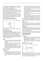
NOTE: • Use a dry cloth to wipe the dirt off the lens of lamp. Be careful not to scratch the lens of lamp, or it may lower the illumination. Reversing switch action 1. Reversing switch lever Selecting the action mode 1 2 1. Action mode changing ring 2. Arrow A B 1 012701 This tool has a reversing switch to change the direction of rotation. Depress the reversing switch lever from the A side for clockwise rotation or from the B side for counterclockwise rotation. When the reversing switch lever is in the neutral position, the switch trigger cannot be pulled. CAUTION: • Always check the direction of rotation before operation. • Use the reversing switch only after the tool comes to a complete stop. Changing the direction of rotation before the tool stops may damage the tool. • When not operating the tool, always set the reversing switch lever to the neutral position. Speed change 1. Speed change lever 1 012736 This tool employs an action mode changing ring. Select one of the three modes suitable for your work needs by using this ring. For rotation only, turn the ring so that the arrow on the tool body points toward the mark on the ring. For rotation with hammering, turn the ring so that the arrow points toward the mark on the ring. For rotation with clutch, turn the ring so that the arrow points toward the mark on the ring. CAUTION: • Always set the ring correctly to your desired mode mark. If you operate the tool with the ring positioned halfway between the mode marks, the tool may be damaged. Adjusting the fastening torque (screwdriver mode " ") 1. Adjusting ring 1 2 2. Graduation 3. Arrow 3 012702 To change the speed, first switch off the tool and then slide the speed change lever to the "2" side for high speed or, "1" side for low speed. Be sure that the speed change lever is set to the correct position before operation. Use the right speed for your job. CAUTION: • Always set the speed change lever fully to the correct position. If you operate the tool with the speed change lever positioned halfway between the "1" side and , "2" side, the tool may be damaged. • Do not use the speed change lever while the tool is running. The tool may be damaged. 012735 The fastening torque can be adjusted in 21 steps by turning the adjusting ring so that its graduations are aligned with the pointer on the tool body. First, slide the action mode change lever to the position of symbol. The fastening torque is minimum when the number 1 is aligned with the pointer, and maximum when the marking is aligned with the pointer. The clutch will slip at various torque levels when set at the number 1 to 21. Before actual operation, drive a trial screw into your material or a piece of duplicate material to determine which torque level is required for a particular application. NOTE: • The adjusting ring does not lock when the pointer is positioned only halfway between the graduations. 6
-
 1
1 -
 2
2 -
 3
3 -
 4
4 -
 5
5 -
 6
6 -
 7
7 -
 8
8 -
 9
9 -
 10
10 -
 11
11 -
 12
12 -
13
-
14
-
15
-
16
-
17
-
18
-
19
-
20
-
21
-
22
-
23
-
24
-
25
-
26
-
27
-
28
-
29
-
30
-
31
-
32
 |
 |
