Makita TW1000 Owners Manual - Page 4
Save These Instructions, Symbols, Functional Description, Assembly - parts
 |
View all Makita TW1000 manuals
Add to My Manuals
Save this manual to your list of manuals |
Page 4 highlights
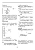
5. Always be sure you have a firm footing. Be sure no one is below when using the tool in high locations. 6. The proper fastening torque may differ depending upon the kind or size of the bolt. Check the torque with a torque wrench. SAVE THESE INSTRUCTIONS WARNING: MISUSE or failure to follow the safety rules stated in this instruction manual may cause serious personal injury. SYMBOLS USD202-2 The followings show the symbols used for tool. V volts A amperes Hz hertz alternating current n no load speed Class II Construction .../min revolutions or reciprocation per minute number of blow FUNCTIONAL DESCRIPTION CAUTION: • Always be sure that the tool is switched off and unplugged before adjusting or checking function on the tool. Switch action 005970 1. Switch trigger B A 1 CAUTION: • Before plugging in the tool, always check to see that the switch trigger actuates properly and returns to the "OFF" position when released. • Change the direction of rotation only when the tool comes to a complete stop. Changing it before the tool stops may damage the tool. The switch is reversible, providing either clockwise or counterclockwise rotation. To start the tool, simply pull the lower part (A) of the switch trigger for clockwise or the upper part (B) for counterclockwise. Release the switch trigger to stop. ASSEMBLY CAUTION: • Always be sure that the tool is switched off and unplugged before carrying out any work on the tool. Installing side grip (auxiliary handle) 005971 1. Side grip 2. Groove 1 2 Fit the side grip into the groove on the hammer case and fasten securely. The grooves for the side grip installation are located in two positions. Install it at the proper position according to your work. Selecting correct socket Always use the correct size socket for bolts and nuts. An incorrect size socket will result in inaccurate and inconsistent fastening torque and/or damage to the bolt or nut. Installing or removing socket CAUTION: • Always be sure that the tool is switched off and unplugged before installing or removing the socket. For socket without O-ring and pin 005973 1. Socket 1 2. Anvil 2 4
-
 1
1 -
 2
2 -
 3
3 -
 4
4 -
 5
5 -
 6
6 -
 7
7 -
 8
8 -
 9
9 -
 10
10 -
11
-
12
-
13
-
14
-
15
-
16
-
17
-
18
-
19
-
20
 |
 |