Makita XPH03MB XPH03Z Instruction Manual - Page 7
Assembly
 |
View all Makita XPH03MB manuals
Add to My Manuals
Save this manual to your list of manuals |
Page 7 highlights
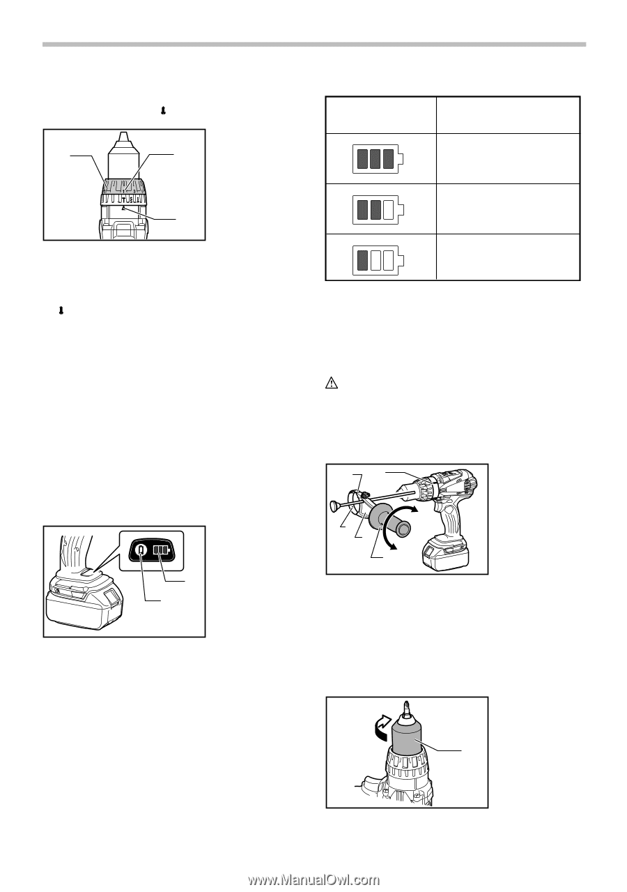
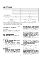
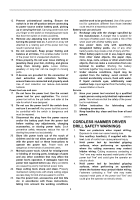
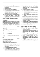
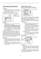
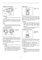
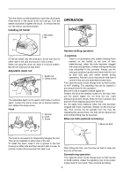
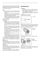
Adjusting the fastening torque (screwdriver mode " ") 1. Adjusting ring 2. Graduation 1 2 3. Arrow LED indicator status Remaining battery capacity About 50% or more 3 012735 The fastening torque can be adjusted in 21 steps by turning the adjusting ring so that its graduations are aligned with the pointer on the tool body. First, slide the action mode change lever to the position of symbol. The fastening torque is minimum when the number 1 is aligned with the pointer, and maximum when the marking is aligned with the pointer. The clutch will slip at various torque levels when set at the number 1 to 21. Before actual operation, drive a trial screw into your material or a piece of duplicate material to determine which torque level is required for a particular application. NOTE: • The adjusting ring does not lock when the pointer is positioned only halfway between the graduations. Empty signal for remaining battery capacity (specific country) Only for tools with the button and LED indicator 1. Button 2. LED indicator 2 1 012714 Stop the tool and with the tool stopped press the button on the switch panel and the remaining battery capacity will be signaled on the panel. The status displayed on the switch panel and the remaining battery capacity is shown in the following table. About 20% - 50% About less than 20% 012023 NOTE: • Before checking the remaining battery capacity, be sure to stop the tool. ASSEMBLY CAUTION: • Always be sure that the tool is switched off and the battery cartridge is removed before carrying out any work on the tool. Installing side grip (auxiliary handle) 2 1 3 4 5 1. Groove 2. Protrusion 3. Steel band 4. Grip base 5. Side grip 012711 Always use the side grip to ensure operating safety. Insert the side grip so that the protrusions on the grip base and steel band fit in between the grooves on the tool barrel. Then tighten the grip by turning clockwise. When you turn the side grip, loosen and remove the grip, then turn the grip and insert it again. Installing or removing driver bit or drill bit 1. Sleeve 1 012697 7
-
 1
1 -
 2
2 -
 3
3 -
 4
4 -
 5
5 -
 6
6 -
 7
7 -
 8
8 -
 9
9 -
 10
10 -
 11
11 -
 12
12 -
13
-
14
-
15
-
16
-
17
-
18
-
19
-
20
-
21
-
22
-
23
-
24
-
25
-
26
-
27
-
28
-
29
-
30
-
31
-
32
 |
 |