Makita XPH03MB XPH03Z Instruction Manual - Page 8
Operation
 |
View all Makita XPH03MB manuals
Add to My Manuals
Save this manual to your list of manuals |
Page 8 highlights
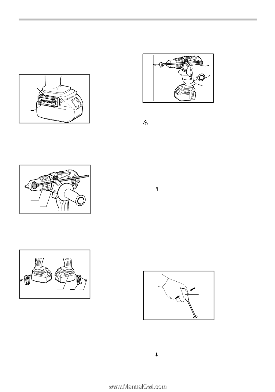
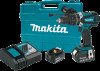
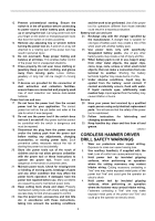
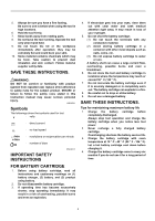
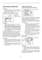
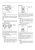
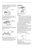
Turn the sleeve counterclockwise to open the chuck jaws. Place the bit in the chuck as far as it will go. Turn the sleeve clockwise to tighten the chuck. To remove the bit, turn the sleeve counterclockwise. Installing bit holder OPERATION 1. Bit holder 2. Bit 1 2 012708 Fit the bit holder into the protrusion at the tool foot on either right or left side and secure it with a screw. When not using the driver bit, keep it in the bit holders. Bits 45 mm long can be kept there. Adjustable depth rod 1. Depth rod 2. Clamp screw 1 2 012712 The adjustable depth rod is used to drill holes of uniform depth. Loosen the clamp screw, set to desired position, then tighten the clamp screw. Hook 1. Groove 2. Hook 3. Screw 012737 Hammer drilling operation CAUTION: • There is a tremendous and sudden twisting force exerted on the tool/bit at the time of hole break-through, when the hole becomes clogged with chips and particles, or when striking reinforcing rods embedded in the concrete. Always use the side grip (auxiliary handle) and firmly hold the tool by both side grip and switch handle during operations. Failure to do so may result in the loss of control of the tool and potentially severe injury. First, slide the action mode change lever so that it points to the marking. The adjusting ring can be aligned in any torque levels for this operation. Be sure to use a tungsten-carbide tipped bit. Position the bit at the desired location for the hole, then pull the switch trigger. Do not force the tool. Light pressure gives best results. Keep the tool in position and prevent it from slipping away from the hole. Do not apply more pressure when the hole becomes clogged with chips or particles. Instead, run the tool at an idle, then remove the bit partially from the hole. By repeating this several times, the hole will be cleaned out and normal drilling may be resumed. Blow-out bulb (optional accessory) 1. Blow-out bulb 1 23 012698 The hook is convenient for temporarily hanging the tool. This can be installed on either side of the tool. To install the hook, insert it into a groove in the tool housing on either side and then secure it with a screw. To remove, loosen the screw and then take it out. 1 002449 After drilling the hole, use the blow-out bulb to clean the dust out of the hole. Screwdriving operation First, slide the action mode change lever so that it points to the marking. Adjust the adjusting ring to the proper torque level for your work. Then proceed as follows. 8
-
 1
1 -
2
-
 3
3 -
 4
4 -
 5
5 -
 6
6 -
 7
7 -
 8
8 -
 9
9 -
 10
10 -
 11
11 -
 12
12 -
 13
13 -
14
-
15
-
16
-
17
-
18
-
19
-
20
-
21
-
22
-
23
-
24
-
25
-
26
-
27
-
28
-
29
-
30
-
31
-
32
 |
 |