Marantz PM8004 PM8004 User Manual - English - Page 7

Part names and functions - amp

Page 7 highlights

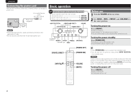
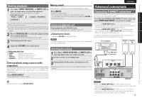
ENGLISH Part names and functions For buttons not explained here, see the page indicated in parentheses ( ). Front panel qw e r t y Rear panel q we r t y u Q5 Q4 Q3 Q2 Q1 Q0 o i u Q2 Q1 Q0 o i q Power switch (ON/OFF 8) w STANDBY indicator 8) Indicates the status of the unit's as follows: • Power "ON" : Off • When the protection circuit is activated : Red (blinking 6) • Standby : Red • Power "OFF" : Off e INPUT SELECTOR knob 9) r Input indicators 8) t MUTE indicator (MUTE 9) y VOLUME control knob 8, 9) u Remote control sensor 3, 10) i BALANCE control knob 8, 9) o SOURCE DIRECT switch/indicator 9) Q0 TREBLE control knob 8, 9) Q1 POWER AMP DIRECT switch/indicator 9) Q2 MID control knob 8, 9) Q3 SPEAKERS A/B switch/indicators 9) Q4 BASS control knob 8, 9) Q5 Headphone jack (PHONES 9) NOTE You can adjust the i BALANCE, Q0 TREBLE, Q2 MID and Q4 BASS control knobs only when o SOURCE DIRECT switch is turned off. q PHONO input connectors 7) w PHONO GND terminal 7) e PRE OUT connectors 10) r POWER AMP DIRECT IN connectors 9) t Speaker system terminals (SPEAKERES SYSTEM A/B 6, 7) y REMOTE CONTROL input/output connectors 10) u AC inlet (AC IN 8) i RECORDER 2 input/output connectors 7) o RECORDER 1 input/output connectors 7) Q0 AUX/DVD input connectors 7) Q1 TUNER input connectors 7) Q2 CD input connectors 7) 4

  • 1
  • 2
  • 3
  • 4
  • 5
  • 6
  • 7
  • 8
  • 9
  • 10
  • 11
  • 12
  • 13
  • 14
  • 15
  • 16
  • 17

4
ENGLISH
q
Power switch (ON/OFF)
······························· (8)
w
STANDBY indicator
······································ (8)
Indicates the status of the unit’s as follows:
• Power “ON” : Off
• When the protection circuit is activated :
Red (blinking)
..............................................
(6)
• Standby : Red
• Power “OFF” : Off
e
INPUT SELECTOR knob
······························· (9)
r
Input indicators
············································ (8)
t
MUTE indicator (MUTE)
······························· (9)
y
VOLUME control knob
····························· (8, 9)
u
Remote control sensor
·························· (3, 10)
i
BALANCE control knob
···························· (8, 9)
o
SOURCE DIRECT switch/indicator
············· (9)
Q
0
TREBLE control knob
······························· (8, 9)
Q
1
POWER AMP DIRECT switch/indicator
······ (9)
Q
2
MID control knob
······································ (8, 9)
Q
3
SPEAKERS A/B switch/indicators
·············· (9)
Q
4
BASS control knob
··································· (8, 9)
Q
5
Headphone jack (PHONES)
·························· (9)
NOTE
You can adjust the
i
BALANCE,
Q
0
TREBLE,
Q
2
MID and
Q
4
BASS control knobs only when
o
SOURCE DIRECT switch is turned off.
Part names and functions
For buttons not explained here, see the page indicated in parentheses (
).
Front panel
t
q
w
e
r
i
Q
1
Q
0
Q
2
Q
4
Q
5
y
u
o
Q
3
q
PHONO input connectors
···························· (7)
w
PHONO GND terminal
·································· (7)
e
PRE OUT connectors
·································· (10)
r
POWER AMP DIRECT IN connectors
·········· (9)
t
Speaker system terminals
(SPEAKERES SYSTEM A/B)
···················· (6, 7)
y
REMOTE CONTROL
input/output connectors
··························· (10)
Rear panel
r
t
y
u
w
e
q
i
o
Q
0
Q
1
Q
2
u
AC inlet (AC IN)
············································· (8)
i
RECORDER 2
input/output connectors
····························· (7)
o
RECORDER 1
input/output connectors
····························· (7)
Q
0
AUX/DVD input connectors
························ (7)
Q
1
TUNER input connectors
····························· (7)
Q
2
CD input connectors
···································· (7)