Marantz SR4400 User Guide - Page 7
Rear Panel - specifications
 |
View all Marantz SR4400 manuals
Add to My Manuals
Save this manual to your list of manuals |
Page 7 highlights
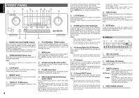
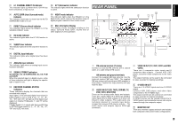
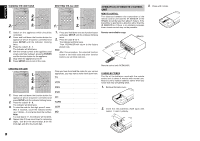
ENGLISH g 6.1 CHANNEL DIRECT IN indicator This indicator lights up when the 6.1CH-IN has been selected as a input source. ¡4 ATT (Attenuation) indicator This indicator lights when the attenuation function is active. REAR PANEL h AUTO.SURR (Auto Surround mode) ¡5 NIGHT mode indicator z x c v indicator. This indicator lights when the SR4400 is in the This indicator illuminates to show that the AUTO Night mode, which reduces the dynamic range of SURROUND mode is in use. digital program material at low volume levels. DVD j DIRECT (Soruce direct) indicator This indicator lights when the SR4400 is in the SOURCE DIRECT mode. ¡6 Main Information Display This display shows messages relating to the status, surround mode, tuner, volume level or other aspects of unit's operation. IN L R IN IN k EQ mode indicator Ω) This indicator lights when the HT-EQ function is active. l SLEEP timer indicator This indicator lights when the seep timer function is in use. CENTER R SURROUND L R FRONT L ⁄2 bn SURROUND SURR. BACK UNSWITCHED 1 MODEL NO. SR4400 SERIAL NO. AC OUTLET (120V 60Hz) ¡0 DIGITAL Input Indicator This indicator lights when digital input has been selected. ⁄1 ⁄0 . , m ⁄3 ¡1 ANALOG input indicator This indicator lights when an analog input source has been selected. ¡2 SIGNAL FORMAT indicators 2 DIGITAL, EX, 2 SURROUND, dts, ES, PCM and 96kHz When the selected input is a digital source, some of these indicators will light to display the specific type of signal in use. ¡3 ENCODED CHANNEL STATUS indicators These indicators display the channels that are encoded with a digital input signal. If the selected digital input signal is Dolby Digital 5.1ch or DTS 5.1ch, "L", "C", "R", "SL", "SR" and "LFE" will light up.If the digital input signal is 2 channel PCM-audio, "L" and "R" will be displayed. If Dolby Digital 5.1ch signal with Surround EX flag or DTS-ES signal comes in, "L", "C", "R", "SL", "S", "SR" and "LFE" will show. z FM antenna terminal (75 ohms) Connect an external FM antenna with a coaxial cable, or a cable network FM source. AM antenna and ground terminals Connect the supplied AM loop antenna. Use the terminals marked "AM" and "GND". The supplied AM loop antenna will provide good AM reception in most areas. Position the loop antenna until you hear the best x AUDIO IN/OUT (CD, TAPE, CDR/MD, TV, DVD, VCR1, DSS/VCR2) These are the analog audio inputs and outputs. There are 7 audio inputs (4 of which are linked to video inputs) and 4 audio outputs (2 of which are linked to video outputs). The audio jacks are nominally labeled for cassette tape decks, compact disc players,DVD players and etc.... The audio inputs and outputs require RCA-type connectors. c VIDEO IN/OUT (TV, DVD, VCR1 and DSS/ VCR2) There are 4 composite video inputs and 2 composite video outputs. Connect VCR, DVD player, and other video components to the video input. The output channels can be used to be connected to video recorder for making recordings. v S-VIDEO IN/OUT There are 2 S-VIDEO inputs and one S-VIDEO output. Connect VCR, DVD player, and other video components to the S-VIDEO input. The output channel can be used to be connected to video recorder for making recordings. S-VIDEO sources can be viewed through the SVIDEO output, and composite sources can only be viewed through the composite output. b MONITOR OUT There are 2 monitor outputs and each one includes both composite video and S-video configurations. 5
-
 1
1 -
 2
2 -
 3
3 -
 4
4 -
 5
5 -
 6
6 -
 7
7 -
 8
8 -
 9
9 -
 10
10 -
 11
11 -
 12
12 -
13
-
14
-
15
-
16
-
17
-
18
-
19
-
20
-
21
-
22
-
23
-
24
-
25
-
26
-
27
-
28
-
29
-
30
-
31
-
32
-
33
-
34
-
35
-
36
 |
 |
