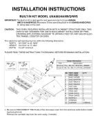
Maytag AMC5143AAS Installation Instructions - Page 2
/64 to 22-19/64, 15/16 to 17-1/64, 3/4 minimum - parts
 |
UPC - 719881136790
View all Maytag AMC5143AAS manuals
Add to My Manuals
Save this manual to your list of manuals |
Page 2 highlights
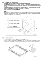
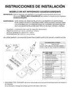
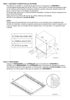
STEP 1 : CABINET OR WALL OPENING Provide an opening in the wall or cabinet, as indicated in SKETCH 1. The depth should be a minimum of 15-3/4". The floor of the opening should be constructed of plywood strong and thick enough to support the weight of the oven and installation job. First, punch the 4-holes using the template, Place the Duct-Rail on the Bottom of the Cabinet. Coincide the Duct-Rail holes with the bottom holes of the Cabinet. Screw the Duct-Rail using Screw B(4EA) NOTE : While the proper functioning of the oven does not require that opening be enclosed (with sides, ceiling and rear partition) this may be required by local code, and it is suggested that the local code be checked for any such requirement. W 22-13/64" to 22-19/64" H 16-15/16" to 17-1/64" D 15-3/4" minimum W D H SKETCH 1 STEP 2 : TRIM ASSEMBLY Position the ASSY TRIM and SIDES as shown in SKETCH 2. Make sure that the ASSY TRIM and SIDES are lined up properly to be neat and symmetrical. Then using Screw B(4EA), screw the parts together at screw locations shown in SKETCH 2. SKETCH 2
-
 1
1 -
 2
2 -
 3
3 -
 4
4 -
 5
5 -
 6
6 -
 7
7 -
 8
8
 |
 |
