Maytag MER5775RAB Installation Manual - Page 4
Range, Installation
 |
View all Maytag MER5775RAB manuals
Add to My Manuals
Save this manual to your list of manuals |
Page 4 highlights
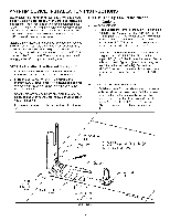
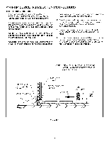
ANTI-TIP DEVICE INSTALLATION INSTRUCTIONS STEP 3 - Range Installation A. For safety considerations as well as optimum performance, adjust the range so it is level and to desired height prior to installing in cabinet opening. Levelness may be checked by placing a spirit level or a large pan of water on the cooktop or oven rack. Adjust the range by tipping it forward or back and rotate the leveling feet as required. Note: A minimum clearance of 1/4" (6mm) is required between the range and the leveling foot that will engage the anti-tip bracket, (see figure 4). Caution: Damage to the range may occur if range is moved or lifted by grasping the main top, backguard or door handle. All free-standing ranges with a glass top have a non lift-up top. Coil tops are lift-up. a. Align the range to its designated location and prepare to slide it back into position. Connect power cord and plug into outlet following guidelines outlined in connecting the range. C. Slide range into place visually inspecting to verify that power cord is freely routed and contained behind range. D. To check the range for proper installation of the anti-tip bracket, use a flashlight and look underneath the bottom of the range to see that one of the rear leveling feet is engaged in the anti-tip bracket slot. SCREWS ENTER WOOD OR METAL. WALL PLATE ART_ 9215-117 NOTE: USE A MINIMUM OF (2) SCREWS TO INSTALL ANTI-TIP BRACKET TO THE WALL OR FLOOR. I-TIP BRACKET SCREW BRACKET TO WALL SLIDE IN TO SECURE R_NTG__ [ 6mm ] 1M/4IN" . FIGURE 4 -4-
-
 1
1 -
 2
2 -
 3
3 -
 4
4 -
 5
5 -
 6
6 -
 7
7 -
 8
8 -
 9
9 -
 10
10 -
11
-
12
-
13
-
14
-
15
-
16
-
17
-
18
-
19
-
20
-
21
 |
 |
