Maytag MGD5500FC Instruction Sheet - Page 10
Style B, Style
 |
View all Maytag MGD5500FC manuals
Add to My Manuals
Save this manual to your list of manuals |
Page 10 highlights
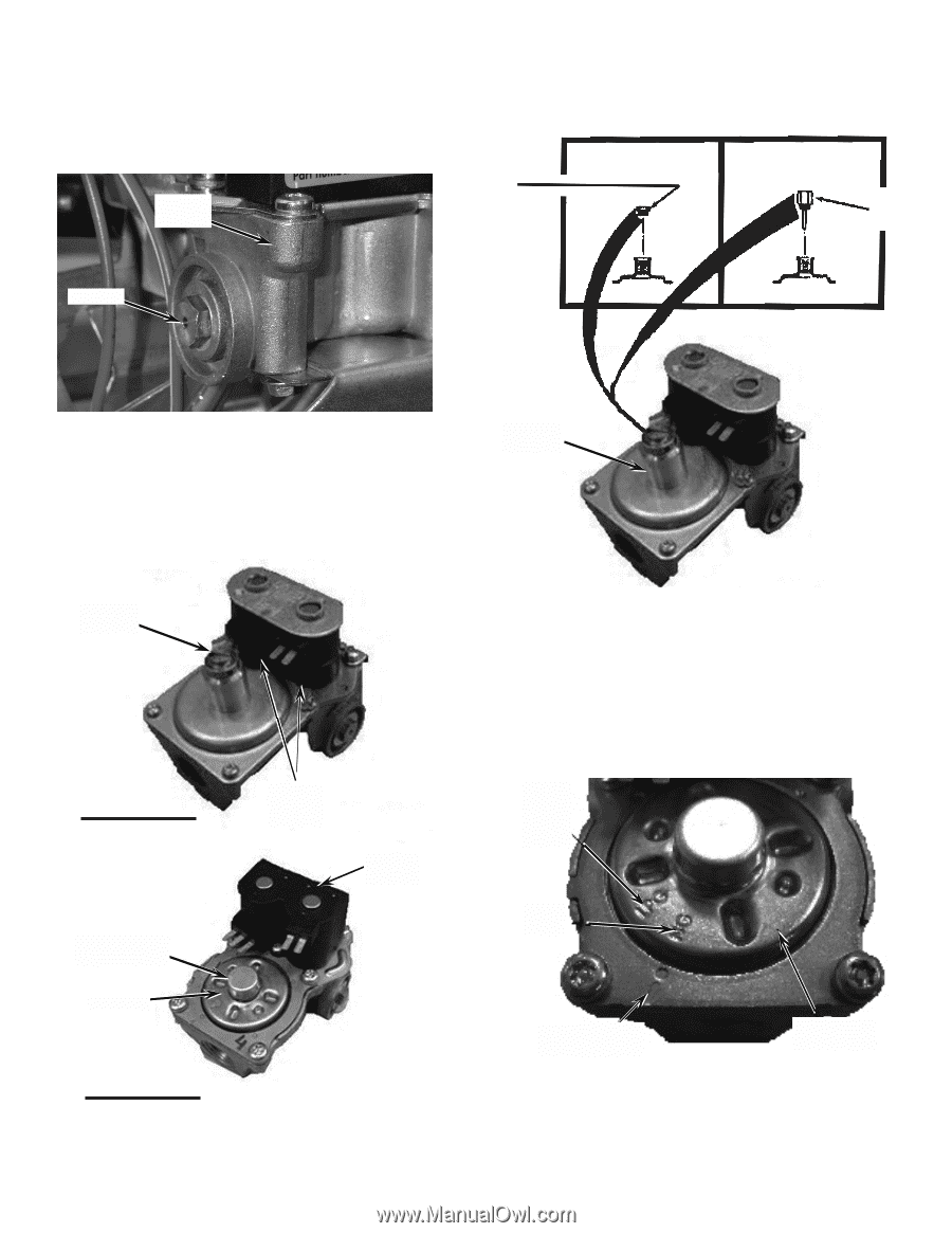
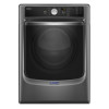
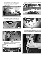
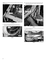
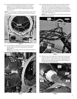
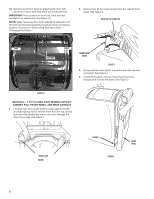
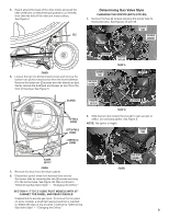
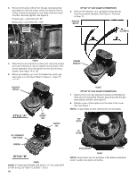
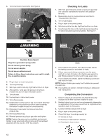
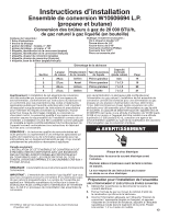
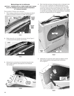
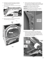
3. Remove the burner orifice from the gas valve assembly and replace it with the proper orifice furnished in this kit. Orifice number is stamped on one edge of the hex head of orifice. Securely tighten. See Figure 3. Propane gas - Use Orifice No. 55. Butane gas - Use Orifice No. .049. GAS VALVE ASSEMBLY STYLE "A" GAS VALVE CONVERSION 6. Remove the regulator vent cap (leak limiting device) from the pressure regulator. See Figure 5. Continue to Step 10. REGULATOR VENT CAP BLOCKING PIN ORIFICE FIGURE 3 4. Slide the burner tube back in place and, using the screws removed in Section 3, step 8, reattach burner tube to the burner assembly. Securely tighten the two (2) mounting screws. See Figure 1A or 1B. 5. Before proceeding, you must first determine which gas valve style is on the dryer. Refer to Figure 4 - Style "A" and "B". PRESSURE REGULATOR REGULATOR VENT CAP STYLE "A" CAP - PERMANENTLY FIXED TO VALVE COVER DIAL TWO SEPARATE COILS ONE-PIECE COIL STYLE "B" FIGURE 4 NOTE: IF YOUR GAS DRYER HAS STYLE "A" FOLLOW STEP 6. FOR STYLE "B" SKIP TO STEPS 7 TO 10. 10 FIGURE 5 STYLE "B" GAS VALVE CONVERSION 7. Observe the cover dial settings indicated as NG (Natural Gas) and LPG (Liquefied Propane gas) along with the gas type setting indicator. See Figure 6. 8. Position a pair of bend pliers into the slots of the cover dial. See Figure 7. NOTE: To gain better access, remove the coil wire leads. "LPG" SETTING "NG" SETTING SETTING INDICATOR COVER DIAL FIGURE 6 NOTE: If bend pliers are not available, a flat-blade screwdriver and/or needle nose pliers will suffice.
-
 1
1 -
2
-
3
-
4
-
 5
5 -
 6
6 -
 7
7 -
 8
8 -
 9
9 -
 10
10 -
 11
11 -
 12
12 -
 13
13 -
 14
14 -
 15
15 -
16
-
17
-
18
-
19
-
20
-
21
-
22
-
23
-
24
-
25
-
26
-
27
-
28
 |
 |