Maytag MMMF6030P Owners Manual
Maytag MMMF6030P Manual
 |
View all Maytag MMMF6030P manuals
Add to My Manuals
Save this manual to your list of manuals |
Maytag MMMF6030P manual content summary:
- Maytag MMMF6030P | Owners Manual - Page 1
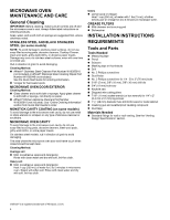
HOOD COMBINATION OWNER'S MANUAL MANUEL DE L'UTILISATEUR DE L'ENSEMBLE FOUR À MICRO-ONDES/HOTTE Table of Contents/Table des matières MICROWAVE OVEN SAFETY 2 Microwave Oven Safety 2 MICROWAVE OVEN MAINTENANCE AND CARE 4 General Cleaning 4 INSTALLATION INSTRUCTIONS 4 REQUIREMENTS 4 Tools and - Maytag MMMF6030P | Owners Manual - Page 2
this manual. � This appliance must be grounded. Connect only to properly grounded outlet. See "GROUNDING INSTRUCTIONS" found or dropped. � This appliance should be serviced only by qualified service personnel. Contact nearest authorized service facility for examination, repair, or adjustment. - Maytag MMMF6030P | Owners Manual - Page 3
paper products, cooking utensils, or food in the cavity when not in use. SAVE THESE INSTRUCTIONS PRECAUTIONS TO AVOID POSSIBLE EXPOSURE TO EXCESSIVE MICROWAVE ENERGY (a) Do not attempt to operate this oven should not be adjusted or repaired by anyone except properly qualified service personnel. 3 - Maytag MMMF6030P | Owners Manual - Page 4
controls are off and the microwave oven is cool. Always follow label instructions on cleaning products. Soap, water, and a soft cloth or W10355010 (not included): See "Online Ordering Information" section from Quick Start Guide to order. NONSTICK CAVITY COATING (on some models) To avoid damage to - Maytag MMMF6030P | Owners Manual - Page 5
-certified parts and accessories for your appliance. Your installation may require additional parts. To order, see the "Online Ordering Information" section of the Quick Start Guide. 5 - Maytag MMMF6030P | Owners Manual - Page 6
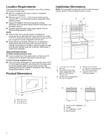
Dimensions" illustration. � Minimum one 2" x 4" (5.1 x 10.2 cm) wood wall stud and minimum 3/8" (1 cm) thickness drywall or plaster/lath within cabinet opening. � Support for weight of 150 lbs (68 kg) which includes microwave oven and items placed inside the microwave oven and upper cabinet - Maytag MMMF6030P | Owners Manual - Page 7
"Online Ordering Information" section of the Quick Start Guide. For other dimension's cabinet, suggest select other Whirlpool Products. B A C A. (Bump out) 13" ≤ DEEPER ≤ 16" B. Cabinet C. Bump put mounting bracket GROUNDING INSTRUCTIONS For a grounded, cord-connected appliance: This appliance - Maytag MMMF6030P | Owners Manual - Page 8
Holes Figure 2 B C A E F A. End holes (on mounting plate) B. Cabinet opening vertical centerline C. Wall stud centerlines C D A E D. Holes for lag screws E. Support tabs F. Mounting plate center markers C D A A E E F NOTE: If wall stud is within 6" (15.2 cm) of the vertical centerline, only - Maytag MMMF6030P | Owners Manual - Page 9
plate center markers A,D E C F A. End holes (on mounting plate) B. Cabinet opening vertical centerline C. Wall stud centerlines A,D E C D. Holes for lag screws E. Support tabs F. Mounting plate center markers Find the Flush Point This product is designed to flush the cabinet, and the flush point - Maytag MMMF6030P | Owners Manual - Page 10
Mark Upper Cabinet 1. Using measuring tape, and clearly mark the vertical centerline of the opening. Make sure it is align with the vertical wall centerline. A Flush to cabinet door E A B A D B C A. Front Edge of Cardboard Plate & Upper Cabinet A. Upper Cabinet Centerline B. Wall Centerline - Maytag MMMF6030P | Owners Manual - Page 11
5. Using a pencil to mark a upper cabinet hole. This step can be skipped if your unit is using recirculation or wall venting installation. NOTE: � If the front edge of the upper cabinet is lower than the back edge, lower the cardboard template so that its top is level with the front edge of the - Maytag MMMF6030P | Owners Manual - Page 12
5. Using the bottom edge of the cardboard plate across the two small lines, draw a mounting plate bottom line. 3. Using a keyhole saw, cut out the rectangular roof venting cutout area. Skip this step if for recirculation venting or wall venting installation. A B C A. Two Small Lines B. - Maytag MMMF6030P | Owners Manual - Page 13
located A & B hole, do not drill A & B hole, and follow the below instruction. In addition to being installed on at least 1 wall stud, the mounting plate must attach least 1 wall stud as well as at both ends. 1. With the support tabs of the mounting plate facing forward, insert 3/16-24 x 3" round - Maytag MMMF6030P | Owners Manual - Page 14
Stud at One End Hole (Figure 3 in Find the wall Stud(s) section) 1. With the support tabs of the mounting plate facing forward, insert a 3/16-24 x 3" round-head bolt before install the microwave oven. And follow the propriated instruction to rotate the blower motor. If for recirculation installation - Maytag MMMF6030P | Owners Manual - Page 15
6. Using diagonal wire cutting pliers, gently snip out the rectangular damper vent covers at the perforations. 10. Reattach the 2 blower screws into the recessed holes in the back of the microwave. A B A. Diagonal wire cutting pliers B. Rectangular damper vent cover 7. Hold the blower motor - Maytag MMMF6030P | Owners Manual - Page 16
Plug into a grounded 3 prong outlet. Do not remove ground prong. Do not use an adapter. Do not use an extension cord. Failure to follow these instructions can result in death, fire, or electrical shock. 14. Plug in the microwave oven. Check if the vent fan runs with abnormal sounds, go back - Maytag MMMF6030P | Owners Manual - Page 17
tabs B. Damper assembly C. #6 x 3/8" Sheet metal screws D. Upper cabinet cutout E. Long tab F. Damper plate 3. Using 2 or more people, lift microwave oven and hang it on support tabs at the bottom of mounting plate. NOTE: To avoid damage to the microwave oven, do not grip or use the door or while - Maytag MMMF6030P | Owners Manual - Page 18
breaker has not tripped. Replace the fuse or reset the circuit breaker. If the problem continues, call an electrician. � Check that the power supply cord is plugged into a grounded 3 prong outlet. � See the User Instructions for troubleshooting information. The installation is now complete. 18 - Maytag MMMF6030P | Owners Manual - Page 19
Save Installation Instructions for future use. A A. 181/8" (46 cm) 121/8" (30.8 cm) A C B D A. Cabinet B. Microwave oven C. Wall or back of the cabinet D. 0.5"-0.75" (1.3-1.9 cm) VENTING DESIGN SPECIFICATIONS Venting Design - Maytag MMMF6030P | Owners Manual - Page 20
A B C D E G F A. Roof cap B. 6" (15.2 cm) minimum diameter round vent C. Elbow (for wall venting only) D. Wall cap E. 31/4" x 10" to 6" (8.3 cm x 25.4 cm to 15.2 cm) rectangular-to-round transition piece F. Vent extension piece, at least 3" (7.6 cm) high G. 3" (7.6 cm) Recommended Standard - Maytag MMMF6030P | Owners Manual - Page 21
qui peut se produire en cas de non-respect des instructions. INSTRUCTIONS IMPORTANTES DE SÉCURITÉ Lors de l'utilisation d'appareils é à effectuer une intervention d'entretien sur cet appareil. Communiquer avec l'entreprise de service autorisé la plus près de chez vous pour la vérification, la - Maytag MMMF6030P | Owners Manual - Page 22
laisser de produits en papier, d'ustensiles de cuisson ou d'aliments dans la cavité lorsque l'appareil n'est pas utilisé. CONSERVER CES INSTRUCTIONS PRÉCAUTIONS POUR ÉVITER TOUTE EXPOSITION ÉVENTUELLE AU RAYONNEMENT EXCESSIF DE MICROONDES ET UTILISER L'APPAREIL SANS DANGER (a) Ne pas tenter de - Maytag MMMF6030P | Owners Manual - Page 23
et que le four à micro-ondes est froid. Toujours suivre les instructions figurant sur les étiquettes des produits de nettoyage. L'usage de savon ément) : Voir la section « Information de commande en ligne » du Guide de démarrage rapide pour commander. REVÊTEMENT INTÉRIEUR ANTIADHÉSIF (sur certains - Maytag MMMF6030P | Owners Manual - Page 24
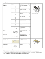
Pièces nécessaires Pièce Ensemble de vis Dessin Description Vis à tête ronde de 3/16 -24 x 3 po Qté Où puis-je trouver? 2 Vis à tête plate de 1/4 -20 x 3 po Rondelles 2 A 2 A. Mousse interne de la cavité Écrou à bascule de 2 3/16 po Tirefonds de 1/4 po x 2 po 4 Clapet Plaque de montage - Maytag MMMF6030P | Owners Manual - Page 25
commander, voir la section « Information de commande en ligne » du Guide de démarrage rapide. Exigences d'emplacement Inspecter l'ouverture où le four po (1 cm) ou plus dans l'ouverture de l'armoire. A B � Capacité de support de charge de 150 lb (68 kg) ceci incluant le four à micro-ondes et les - Maytag MMMF6030P | Owners Manual - Page 26
la section « Information de commande en ligne » du Guide de démarrage rapide. Pour d'autres dimensions d'armoire, PROFOND ≤ 16 po B. Armoire C. Support de montage de bourrelet Spécifications électriques utiliser de rallonge. Le non-respect de ces instructions peut causer un décès, un incendie ou une - Maytag MMMF6030P | Owners Manual - Page 27
plaque de montage) B. Axe vertical central de l'ouverture dans l'armoire C. Axe vertical de montant de cloison C D A E D. Trous pour tirefonds E. Pattes de support F. Marquage du centre sur plaque de montage C D A A E E F REMARQUE : Si le montant de cloison se trouve à moins de 6 po (15,2 cm - Maytag MMMF6030P | Owners Manual - Page 28
de montage) B. Axe vertical central de l'ouverture dans l'armoire C. Axe vertical de montant de cloison A,D E C D. Trous pour tirefonds E. Pattes de support F. Marquage du centre sur plaque de montage A,D E C F A. Trous d'extrémité (sur la plaque de montage) B. Axe vertical central de l'ouverture - Maytag MMMF6030P | Owners Manual - Page 29
Maque pour l'armoire supérieure 1. Utiliser un mètre-ruban pour marquer clairement la position de l'axe central vertical de l'ouverture. S'assurer qu'elle s'aligne avec l'axe central vertical au mur. A En affleurement avec la porte d'armoire E A B A D B C A. Axe central de l'armoire supé - Maytag MMMF6030P | Owners Manual - Page 30
4. Utiliser un crayon pour marquer le trou du cordon d'alimentation et les deux trous des écrous de montage. B Marquer au crayon le trou d'évacuation sur le mur (pour installation avec décharge murale seulement). Sauter cette étape si l'appareil effectue la recirculation de l'air ou si l'évacuation - Maytag MMMF6030P | Owners Manual - Page 31
4. Trouver et dessiner les deux petites lignes par les deux lignes B de position inférieure de la plaque de carton. A A. Ligne de position du bas de la plaque de carton 5. Utiliser le bord inférieur de la plaque de carton entre les deux petites lignes pour dessiner une ligne du bas de la plaque - Maytag MMMF6030P | Owners Manual - Page 32
perceuse pour percer les trous A, B, H et J. S'il n'y a pas de montants de cloison aux emplacements A et B, ne pas percer les trous A et B et suivre les instructions suivantes. En plus d'être fixé sur au moins un montant de cloison, on doit également fixer la plaque de montage sur le mur au niveau - Maytag MMMF6030P | Owners Manual - Page 33
(illustration 3 dans la section Trouver les montants de cloison) 1. Alors que les pattes de support de la plaque de montage sont orientées vers l'avant, insérer une vis à tête avant d'installer le four à micro-ondes. Suivre les instructions appropriées pour réorienter le moteur du ventilateur. Pour - Maytag MMMF6030P | Owners Manual - Page 34
à la verticale, comme illustré. A 5. Sortir le moteur du four à micro-ondes et le garder pour plus tard. A A. Plaque de support du clapet 3. Retirer 2 vis de ventilateur fixant le moteur du ventilateur au four à micro-ondes et les garder pour plus tard. A. Moteur de ventilateur 6. Utiliser - Maytag MMMF6030P | Owners Manual - Page 35
le fil du moteur de ventilateur dans le connecteur. A B A B A. Vis B. Trous de vis du moteur de ventilateur 12. Remettre la plaque de support du clapet à sa position horizontale d'origine. A A. Fil du moteur de ventilateur B. Connecteur 10. Fixer de nouveau les 2 vis du ventilateur dans les - Maytag MMMF6030P | Owners Manual - Page 36
pour que le moteur ne puisse pas bouger. 7. Remettre la plaque de support du clapet à sa position horizontale d'origine. Risque de décharge électrique d'adaptateur. Ne pas utiliser de rallonge. Le non-respect de ces instructions peut causer un décès, un incendie ou une décharge électrique. 14. - Maytag MMMF6030P | Owners Manual - Page 37
déplacer et installer l'appareil. Le non-respect de cette instruction peut causer une blessure au dos ou d'autres blessures. 3/8 po D. Ouverture découpée dans l'armoire supérieure E. Patte longue F. Plaque de support du clapet 3. À l'aide de 2 personnes ou plus, soulever le four à micro-ondes - Maytag MMMF6030P | Owners Manual - Page 38
ée à la terre. Ne pas enlever la prise de liaison à la terre. Ne pas utiliser d'adaptateur. Ne pas utiliser de rallonge. Le non-respect de ces instructions peut causer un décès, un incendie ou une décharge électrique. 3. Brancher le four à micro-ondes sur une prise à trois alvéoles reliée à la terre - Maytag MMMF6030P | Owners Manual - Page 39
Conserver les instructions d'installation pour une éventuelle réutilisation future. A A. 18 1/8 po (46 cm) 12 1/8 po (30,8 cm) � On déconseille l'emploi d'un conduit métallique flexible. � Pour éviter d'éventuelles détériorations - Maytag MMMF6030P | Owners Manual - Page 40
A B C D E G F A. Bouche de décharge sur toit B. Conduit rond dia. 6 po (15,2 cm) minimum C. Coude (pour décharge murale uniquement) D. Bouche de décharge murale E. Raccord de transition rectangulaire/rond de 3 1/4 po x 10 po à diamètre de 6 po (8,3 cm x 25,4 cm à 15,2 cm) F. Raccord d'
-
 1
1 -
 2
2 -
 3
3 -
 4
4 -
 5
5 -
 6
6 -
 7
7 -
8
-
9
-
10
-
11
-
12
-
13
-
14
-
15
-
16
-
17
-
18
-
19
-
20
-
21
-
22
-
23
-
24
-
25
-
26
-
27
-
28
-
29
-
30
-
31
-
32
-
33
-
34
-
35
-
36
-
37
-
38
-
39
-
40
 |
 |

MICROWAVE OVEN HOOD COMBINATION
OWNER’S MANUAL
MANUEL DE L’UTILISATEUR DE L’ENSEMBLE FOUR À
MICRO-ONDES/HOTTE
Table of Contents/Table des matières
MICROWAVE OVEN SAFETY
.............................................
2
Microwave Oven Safety
..................................................
2
MICROWAVE OVEN MAINTENANCE AND CARE
..................
4
General Cleaning
...........................................................
4
INSTALLATION INSTRUCTIONS
........................................
4
REQUIREMENTS
.............................................................
4
Tools and Parts
.............................................................
4
Location Requirements
...................................................
6
Product Dimensions
.......................................................
6
Installation Dimensions
...................................................
6
Electrical Requirements
..................................................
7
INSTALLATION
...............................................................
7
Prepare Microwave Oven Hood Combination
.......................
7
Installation Types
...........................................................
8
Find the Cardboard Plate
.................................................
8
Find the Wall Stud(s)
......................................................
8
Find the Flush Point
........................................................
9
Mark Upper Cabinet
.....................................................
10
Mark Rear Wall
............................................................
11
Drill holes in Upper Cabinet
............................................
12
Drill holes in Rear Wall
..................................................
12
Attach Mounting Plate to Wall
.........................................
13
Rotate Blower Motor
.....................................................
14
Install Damper Assembly
...............................................
17
Install the Microwave Oven
............................................
17
Complete Installation
....................................................
18
VENTING DESIGN SPECIFICATIONS
................................
19
Venting Design Specifications
.........................................
19
SÉCURITÉ DU FOUR À MICRO-ONDES
............................
21
Sécurité du four à micro-ondes
.......................................
21
ENTRETIEN ET RÉPARATION DU FOUR À MICRO-
ONDES
........................................................................
23
Nettoyage général
........................................................
23
INSTRUCTIONS D’INSTALLATION
...................................
23
SPÉCIFICATIONS
..........................................................
23
Outils et pièces
............................................................
23
Exigences d’emplacement
.............................................
25
Dimensions du produit
..................................................
25
Dimensions d’installation
...............................................
25
Spécifications électriques
..............................................
26
INSTALLATION
.............................................................
26
Préparation de l’ensemble four à micro-ondes/hotte
............
26
Type d’installation
........................................................
27
Trouver la plaque de carton
............................................
27
Trouver les montants de cloison
......................................
27
Trouver le point d’affleurement
........................................
28
Maque pour l’armoire supérieure
.....................................
29
Marque sur le mur arrière
..............................................
30
Percer les trous dans l’armoire supérieure
.........................
31
Perçage de trous dans le mur arrière
................................
31
Fixation de la plaque de montage au mur
..........................
32
Réorientation du moteur du ventilateur
.............................
33
Installation du clapet antiretour
.......................................
36
Installation du four à micro-ondes
....................................
37
Achever l’installation
.....................................................
38
SPÉCIFICATION DE LA CONCEPTION DU CIRCUIT
D’ÉVACUATION
.............................................................
39
Spécification de la conception du circuit d’évacuation
..........
39
IMPORTANT:
Save for local electrical inspector’s use.
IMPORTANT :
À conserver pour consultation par l'inspecteur local des installations électriques.
W11595046A