Meade Infinity 80mm User Manual - Page 5
Setting Up Your Tripod, Attach The Accessory Tray, Attach The Slow-motion Controls
 |
View all Meade Infinity 80mm manuals
Add to My Manuals
Save this manual to your list of manuals |
Page 5 highlights
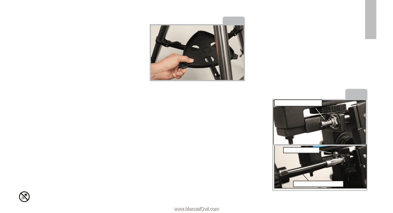
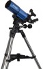
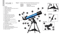
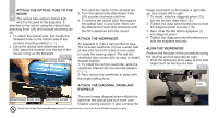
SETTING UP YOUR TRIPOD The tripod is the basic support for your telescope and comes pre-assembled from the factory; except for the accessory tray. The tripod height may be adjusted so that you can view comfortably. Note: Number in brackets, e.g., (3), refer to the item numbers in Fig. 1. 1. To setup the tripod, spread the legs out evenly and place it on a solid surface. 2. Set the height of your tripod: a. Rotate and loosen the leg lock thumbscrew (18) to unlock the leg lock. b. Slide the inner portion of the leg (17) in or out to the desired length. Repeat for the other two legs. c. Rotate and tighten the leg lock thumbscrew to re-lock the leg lock. d. Repeat for the other two legs. ATTACH THE ACCESSORY TRAY The accessory tray attaches at the center of the tripod legs and is a convenient place to hold eyepieces and other Meade accessories while observing, such as the Barlow lens. To attach, place the hole in the center of the Fig. 2 accessory tray over the attachment point as shown in Fig 2. Then rotate the tray until the wings of the tray snap into place on the tripod leg brace supports(9). To remove the tray, rotate the tray so it unlocks from the leg brace supports (9), then remove. ATTACH THE SLOW-MOTION CONTROLS The slow motion control cables (11 & 12) allow you to make fine adjustments to the pointing position of the optical tube. When viewing objects in the night sky, you will notice that the object moves slowly in the eyepiece. This is caused by the Earths rotation. Use the slow motion controls to follow (or "track") these Looking at or near the Sun will cause irreversible damage to your eye. Do not point this telescope at or near the Sun. Do not look through the telescope as it is moving. objects as you observe. Note that each axis has its own slow motion control which is independently controlled. 3 To install, attach the flexible cables (11 & 12) to the mount as shown in Fig 3. The cables are secured in place with a firm tightening of the thumbscrews located at the attachment ends of each cable. Attachment point Fig. 3 Thumbscrew Slow motion cable
-
 1
1 -
 2
2 -
 3
3 -
 4
4 -
 5
5 -
 6
6 -
 7
7 -
 8
8 -
 9
9 -
 10
10 -
 11
11 -
12
-
13
-
14
-
15
-
16
-
17
-
18
-
19
-
20
 |
 |