Meade LX600-ACF 10 inch User Manual - Page 47
Maintenance
 |
View all Meade LX600-ACF 10 inch manuals
Add to My Manuals
Save this manual to your list of manuals |
Page 47 highlights
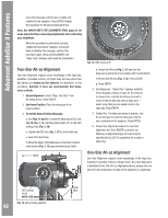
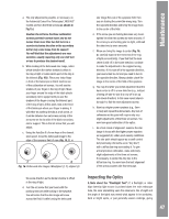
a. The only adjustments possible, or necessary, on the Advanced Coma-Free Telescopes LX600 ACF models are from the three screws (as shown in Fig 15.) Caution: Do not force the three collimation screws past their normal travel and do not loosen them more than two full turns in a counterclockwise direction or the secondary mirror may come loose from its support. You will find that the adjustments are very sensitive, usually requiring only one-half turn or less to produce the desired result. b. While looking at the defocused star image, notice which direction the darker shadow is offset in the ring of light or notice which part of the ring is the thinnest (Fig. 16,1). Place your index finger in front of the telescope so that it touches one of the collimation set screws. You will see the shadow of your finger in the ring of light. Move your finger around the edge of the black plastic secondary mirror support until you see the shadow of the finger crossing the thinnest part of the ring of light. At this point, look at the front of the telescope where your finger is aiming. It will either be pointing directly at a set screw, or it will be between two set screws aiming at the set screw on the far side of the black secondary mirror support. This is the set screw that you will adjust. c. Using the AutoStar II's Arrow keys at the slowest slew speed, move the defocused image to the edge of the eyepiece field of view (Fig. 16, 2), in 1 2 3 Fig. 16. Defocused star images. Misaligned (1, 2), aligned (3) the same direction as the darker shadow is offset in the ring of light. d. Turn the set screw that you found with the pointing exercise while looking in the eyepiece. You will notice that the star image will move across the field. If while turning the defocused star image flies out of the eyepiece field, then you are turning the screw the wrong way. Turn the opposite direction and bring the image back to the center of the field. e. If the screw you are turning becomes very loose, tighten the other two screws by even amounts. If the screw you are turning gets too tight, unthread the other two by even amounts. f. When you bring the image to center (Fig. 16, 3), carefully examine the evenness of the ring of light (concentricity). If you find that the dark center is still off in the same direction, continue to make the adjustment in the original turning direction. If it is now off in the opposite direction, you have turned too far and you need to turn in the opposite direction. Always double check the image in the center of the field of the eyepiece. g. You may find after your initial adjustment that the dark center is off in a new direction (e.g., instead of being off side-to-side it is now off in an upand-down direction). In this case repeat steps b through f to find the new adjustment screw. h. Now try a higher power eyepiece (e.g., 9mm or less) and repeat the above tests. Any lack of collimation at this point will require only very slight adjustments of the three set screws. You now have good collimation of the optics. i. As a final check of alignment, examine the star image in focus with the higher power eyepiece as suggested (h), under good viewing conditions. The star point should appear as a small central dot (commonly referred to as an "Airy disc") with a diffraction ring surrounding it. To give a final precision collimation, make extremely slight adjustments of the three set screws, if necessary, to center the Airy disc in the diffraction ring. You now have the best alignment of the optics possible with this telescope. Inspecting the Optics A Note about the "Flashlight Test": If a flashlight or other high-intensity light source is pointed down the main telescope tube, the view (depending upon the observer's line of sight and the angle of the light) may reveal what appear to be scratches, dark or bright spots, or just generally uneven coatings, giving 47 Maintenance
-
 1
1 -
2
-
3
-
4
-
5
-
6
-
7
-
8
-
9
-
10
-
11
-
12
-
13
-
14
-
15
-
16
-
17
-
18
-
19
-
20
-
21
-
22
-
23
-
24
-
25
-
26
-
27
-
28
-
29
-
30
-
31
-
32
-
33
-
34
-
35
-
36
-
37
-
38
-
39
-
40
-
41
-
 42
42 -
 43
43 -
 44
44 -
 45
45 -
 46
46 -
 47
47 -
 48
48 -
 49
49 -
 50
50 -
 51
51 -
 52
52 -
53
-
54
-
55
-
56
-
57
-
58
-
59
-
60
-
61
-
62
-
63
-
64
-
65
-
66
-
67
-
68
-
69
-
70
-
71
-
72
 |
 |
