Meade Pier LX600-ACF 16 inch Instruction Manual - Page 12
Attaching the Fork
 |
View all Meade Pier LX600-ACF 16 inch manuals
Add to My Manuals
Save this manual to your list of manuals |
Page 12 highlights
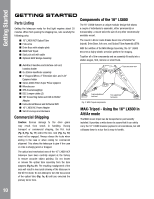
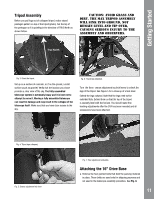
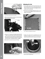
AutoStar #G4et9t7inHgASNtDarBtOedX Attaching the Fork a. Place the single-piece fork onto the top of the drive base. One side of the base of the fork has a cutout to allow clearance for the R.A. lock and R.A. slow-motion control (Fig. 13), which are located on top of the drive base. b. Bolt the fork to the drive base using the four 3/8"-16 x 3/4" long socket cap screws (Fig. 13). Using the supplied hex key, tighten to a firm feel only. Fig. 8: Remove the pointed bolts from the drive base. b. With the tripod orientated as described on the previous page, place the drive base onto the tripod. Drive base Adapter Plate Fig. 9: Attach the drive base to the tripod. Fig. 11: Remove the for thumbscrews from the plate. c. Position the 16" drive base with drivebase adapter plate (Fig 1, #44) onto the field tripod, with the power panel facing South. Secure the drive base using the three attachment bolts. Thread these bolts up through the underside of the tripod head into the drive base. Firmly tighten these bolts. See Fig. 2. d. Note the DB-15 connector at the center of the base. c. Unscrew and remove the four thumbscrews from the rectangular plate (Fig. 11) in the center of the fork arms. Remove the plate. Note the DB-15 plug under the fork plate. Connector thumbscrew DB-15 Connector 12 Fig. 10: Secure the drive base to the tripod by tightening the lever. Fig. 12: View beneath plate (fork base not shown for clarity sake): Attach the DB-15 connector underneath the plate.
-
 1
1 -
2
-
3
-
4
-
5
-
6
-
 7
7 -
 8
8 -
 9
9 -
 10
10 -
 11
11 -
 12
12 -
 13
13 -
 14
14 -
 15
15 -
 16
16 -
 17
17 -
18
-
19
-
20
-
21
-
22
-
23
-
24
-
25
-
26
-
27
-
28
 |
 |
