Meade Pier LX600-ACF 16 inch Instruction Manual - Page 19
Setting the Wedge Latitude Range, MAX-Wedge Adapter Plate
 |
View all Meade Pier LX600-ACF 16 inch manuals
Add to My Manuals
Save this manual to your list of manuals |
Page 19 highlights
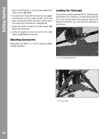
Appendix A: Polar Mode with MAX-Wedge Fig. 24: Tripod lock levers. Tighten (rotate) the tripod lock knobs below the Wedge to a "tight" feel by first loosely tightening all three knobs, then further tightening all three securely. Latitude Lock Bolt "Porthole" Latitude Range Bolts Latitude Lock Bolt Fig. 25: Latitude adjustment. Setting the Wedge Latitude Range The telescope comes set for mid-range latitudes (30° to 60°). If you need to set for low range or high range, loosen all four latitude lock screws (2 on each side) remove the 4 latitude bolts from each side of the wedge (8 total) using a supplied hex Latitude Adjust Knob Fig. 27: MAX-Wedge latitude adjustment knob. wrench (see photo above). The wedge will now swing freely. Swing the wedge so that the bolt portholes match up with another set of bolt holes on the underneath plate (there are three sets of bolt holes, one for each latitude range). Move the wedge until it lines up your latitude tick mark with the indicator on the latitude scale. Replace and tighten the latitude bolts. Note: If you are setting for low-range latitude, you will need to replace only three bolts on each side. There isn't a fourth hole on either side. Relock latitude locks screws. Fine tune the latitude adjustment using the Latitude Adjustment knobs. See appendix B, if you need help reading the latitude scale. • Is your telescope pointing North? • Is your telescope level? • Make sure you are pointing Toward True North and are level before proceeding. 1/2 -13 x 2" Hex head bolts to secure plate to drive base. Six (6) required. Dovetail Adapter Plate Move and line up latitude tick mark with indicator Fig. 26: Latitude scale and indicator. Drive base Adapter Plate Fig. 28: Attach the MAX-Wedge adapter plate. Note: Drive base is shown in upside down position. MAX-Wedge Adapter Plate In order to secure the 16" drive base to the MAX-Wedge, two adapter plates are used. The drive base adapter plate(Fig 1, 44) connects directly to the drive base using three 1/2-13 x 5/8" socket cap screws. 19
-
 1
1 -
2
-
3
-
4
-
5
-
6
-
7
-
8
-
9
-
10
-
11
-
12
-
13
-
 14
14 -
 15
15 -
 16
16 -
 17
17 -
 18
18 -
 19
19 -
 20
20 -
 21
21 -
 22
22 -
 23
23 -
 24
24 -
25
-
26
-
27
-
28
 |
 |
