Metabo DSD 250 Operating Instructions - Page 13
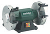
Special Product Features, Initial Operation - bench grinder
 |
View all Metabo DSD 250 manuals
Add to My Manuals
Save this manual to your list of manuals |
Page 13 highlights
ENGLISH ENG 19 Rubber stopper * * depending on equipment/not in scope of delivery 6 Special Product Features • Bayonet catch on safety guards ensures quick, easy replacement of grinding wheels • Low-noise, low-vibration, maintenance-free induction motor • Vibration-absorbing rubber feet BS 175, DS 175, DS 200, DSD 200, DSD 250, TNS 175: • Safety guards with extraction connection piece TNS 175: • Slow-speed, fine grained wet grinding disc and high-speed dry grinding wheel • Corrosion-resistant water bath container BS 175: • Large, tilting belt grinding arm (continuously variable by 90°) for processing wood and metal workpieces 7 Initial Operation 7.1 Power supply Before plugging in, check that the rated mains voltage and mains frequency, as stated on the rating label, match with your power supply. The grinder complies with protection class I and must therefore only be connected to sockets earthed according to specifications. DSD 200, DSD 250 (three-phase version): Ensure that the grinding wheels have the correct direction of rotation (the correct direction of rotation is indicated by an arrow on the side safety guards). If a grinding wheel is rotating in the wrong direction: Unplug the grinder. The plug comprises of two phase conducting pins that are mounted on a rotating socket (phase changing switch). Use a Phillips screwdriver to rotate this socket. 7.2 Installing workpiece support Install workpiece support (8) as shown in illustrations A, page 3. 7.3 Fitting spark deflector and eye preservers Install the spark deflector (10) and eye preservers (9) as shown in illustrations B, page 3. 7.4 Installing machine safely Place the machine on a stable workbench. Ensure that the machine is securely seated. The machine can also be bolted down (screws not included in the scope of delivery). To do this, fasten the securing screws through the holes in the rubber feet. If a stand or wall bracket is used (see Accessories chapter): bolt down the machine. 7.5 Dust extraction connection (depending on equipment) If your machine is not equipped with a dust extraction connection (6), fit an extraction device that is suitable for double-wheeled bench grinders. Inner diameter of extraction connection piece: 35 mm. Before switching on the machine, ensure that the extraction device is connected and being used correctly. 7.6 Test run Check the grinding wheels before initial use. Test run A test run of approx. 5 min without load must be carried out before initial use. All persons must stay clear of the danger zone when this is performed. . 8 Use 8.1 Adjusting the workpiece support Adjust the workpiece supports (8) frequently to compensate for wear of the grinding wheels (4). The distance between the workpiece support and grinding material must be as small as possible and never greater than 2 mm (see illustration C, page 3). If the grinding wheel is so badly worn that the maximum distance of 2 mm can no longer be maintained, the grinding wheel must be replaced. 8.2 Adjusting the spark deflector Adjust the spark deflectors (10) regularly to compensate for wear on the grinding wheels (4). Release the 2 screws on the spark deflector and shift the spark deflector. The distance between the spark deflector and grinding wheel must be as small as possible and never greater than 2 mm (see illustration C, page 3). 13
-
 1
1 -
2
-
3
-
4
-
5
-
6
-
7
-
 8
8 -
 9
9 -
 10
10 -
 11
11 -
 12
12 -
 13
13 -
 14
14 -
 15
15 -
 16
16 -
 17
17 -
 18
18 -
19
-
20
-
21
-
22
-
23
-
24
-
25
-
26
-
27
-
28
-
29
-
30
-
31
-
32
-
33
-
34
-
35
-
36
-
37
-
38
-
39
-
40
-
41
-
42
-
43
-
44
-
45
-
46
-
47
-
48
-
49
-
50
-
51
-
52
-
53
-
54
-
55
-
56
-
57
-
58
-
59
-
60
-
61
-
62
-
63
-
64
-
65
-
66
-
67
-
68
-
69
-
70
-
71
-
72
-
73
-
74
-
75
-
76
-
77
-
78
-
79
-
80
-
81
-
82
-
83
-
84
-
85
-
86
-
87
-
88
-
89
-
90
-
91
-
92
-
93
-
94
-
95
-
96
-
97
-
98
-
99
-
100
 |
 |
