Metabo MAG 50 Operating Instructions 2 - Page 10
Overview, Commissioning - magnetic drill
 |
View all Metabo MAG 50 manuals
Add to My Manuals
Save this manual to your list of manuals |
Page 10 highlights
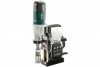
ENG ENGLISH The surface for the electromagnet must be clean and flat. The magnet holding power depends on material thickness and condition. Paint, zinc and oxide layers reduce the magnet holding power. Do not expose the magnetic drill stand to rain and do not use in wet or potentially explosive rooms. Before any setting or maintenance work on the drill, pull the drill plug from the socket of the magnetic drill stand. Caution! When the mains plug of the magnetic drill stand is disconnected, the magnet loses its holding power. Observe the Operating Instructions of the drill. At the socket (4), only connect drills with the following current consumption: at 110-120 V: maximum 12 ampere; at 220-240 V: maximum 9 ampere. Before use, always check that the eccentric (13) is firmly clamped so that accidental displacement or rotation of the upper section is not possible. Wear protective goggles. Danger - electrical voltage. Danger - magnetic field. Persons with pacemakers prohibited. 5 Overview See page 3. 1 Snap hook of safety chain 2 Safety chain 3 Holding points 4 Drill socket 5 Slide plate 6 Threaded pins for adjusting backlash of the side plate 7 Lever 8 Spindle 9 Switch for switching on the drill 10 Switch for switching off the drill 11 Switch for switching magnet on and off 12 Magnet block / Magnet 13 Eccentric 14 Screw for securing the drill 15 Holder for securing the drill 16 Clamping ring 17 Clamping ring screw 6 Commissioning Before plugging in, check to see that the rated mains voltage and mains frequency, as specified on the rating label, match your power supply. Check the unit for possible damage: Before using the unit, protective devices or slightly damaged components must be carefully checked for perfect and specified operation. Check that moving parts are in perfect working order and do not jam and check whether parts are damaged. All parts must be correctly installed and fulfil all conditions necessary to ensure perfect operation of the unit. Damaged protective devices and parts must be repaired or replaced according to specifications by an authorised specialist workshop. 6.1 Assembly 1. Screw the 3 levers (7) firmly into the spindle (8). 2. Inserting drill B 32/3: - Unscrew additional handle from drill (observe the Operating Instructions of the drill). - Align the drill so that the thread (into which the additional handle was screwed) faces the holder (15). - Insert the drill collar into the clamping ring (16). - Screw the drill with screw (14) onto holder (15). - Tighten screw (17) of clamping ring. - Press switch (10) and set switch (11) to "0" (so that the drill cannot start up). - Insert mains plug of drill into socket (4) of magnetic drill stand. - Set continuous operation at the drill. (Observe the Operating Instructions of the drill). 6.2 Mains connection The magnetic drill stand is in protection class I and must therefore only be connected to sockets earthed according to specifications. If an extension cord is needed, it must be a threecore lead with a protective (earth) contactor that is properly connected to both the plug and the coupler of the cord. When working outdoors, only use the correspondingly marked extension cable approved for this purpose. Regularly check extension cables and replace if damaged. 10
-
 1
1 -
2
-
3
-
4
-
 5
5 -
 6
6 -
 7
7 -
 8
8 -
 9
9 -
 10
10 -
 11
11 -
 12
12 -
 13
13 -
 14
14 -
 15
15 -
16
-
17
-
18
-
19
-
20
-
21
-
22
-
23
-
24
-
25
-
26
-
27
-
28
-
29
-
30
-
31
-
32
-
33
-
34
-
35
-
36
-
37
-
38
-
39
-
40
-
41
-
42
-
43
-
44
-
45
-
46
-
47
-
48
-
49
-
50
-
51
-
52
-
53
-
54
-
55
-
56
-
57
-
58
-
59
-
60
-
61
-
62
-
63
-
64
-
65
-
66
-
67
-
68
-
69
-
70
-
71
-
72
-
73
-
74
-
75
-
76
-
77
-
78
-
79
-
80
 |
 |
