Metabo MFE 30 Operating Instructions - Page 16
Initial operation, Power supply, Chase width - set
 |
View all Metabo MFE 30 manuals
Add to My Manuals
Save this manual to your list of manuals |
Page 16 highlights
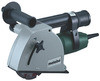
ENGLISH Ensure that the diamond cutting blades are installed in accordance with the manufacturer's instructions. Prior to use, ensure that the diamond cutting blades are properly fitted and secured. Run the machine in idling for 60 seconds in a safe position and bring to a standstill immediately if there are significant vibrations or if other deficiencies are determined. If such a situation occurs, check the machine to determine the cause. Never switch on the machine without the protective cover installed. The material being processed must be firmly secured. Ensure that sparks produced during work do not constitute a risk to the user or other personnel and are not able to ignite inflammable substances. Endangered areas must be protected with flameresistant covers. Make sure that fire-risk areas are always provided with suitable fire extinguishers. When working in dusty conditions, ensure that ventilation openings are not blocked. If it becomes necessary to remove dust, first disconnect the power tool from the mains supply (use nonmetallic objects) and avoid damaging internal components. The diamond cutting blades continue running after the machine has been switched off. - slowly turn the front diamond cutting blade (with the other hand) until the spindle-lock button engages. - Hold the spindle-lock button down and remove the clamping nut (11) with the pin spanner supplied. Caution! Never press the spindle-lock button (12) while the machine is running (and when it is drifting to a stop)! 15 } 16 11 Figure 1 a Figure 1 b 5 Initial operation Before plugging in check to see that the rated mains voltage and power frequency, as stated on the rating label, match with your power supply. Figure 1 c 6 Power supply This wall chaser is equipped with an electronic starting-current limitation. It can therefore be oprated on circuits protected by a miniature circuit breaker of type H characteristics or a fast acting fuse. 7 Chase width See page 2. - unplug, - remove the hex. socket head cap screw (3), - loosen the hex. socket head cap screw (7) and - set the guard (9) and guide shoe (10) - approx. as shown on page 2 - so that the diamond cutting blades are reradily accessible; then - press the spindle-lock button (12) and Figure 1 d The support flange (15) must always be placed with the flange outwards (as illustrated in figures 1a - 1d) onto the spindle. Make sure the support flange does not turn on the spindle. Arrangement of spacer rings (16) and diamond cutting blades (for required chase width) as illustrated in figures 1a - 1d.The direction of rotation of the diamond cutting blades is indicated by arrows on both the blades and guard (9). Lock the spindle by pressing the spindle-lock button (12), then tighten the clamping nut (11) with the pin spanner. Then - swing guard (9) and guide shoe (10) back, - turn hex. socket head cap screw (3) back in and - tighten the hex. socket head cap screw (7) 16
-
 1
1 -
2
-
3
-
4
-
5
-
6
-
7
-
8
-
9
-
10
-
 11
11 -
 12
12 -
 13
13 -
 14
14 -
 15
15 -
 16
16 -
 17
17 -
 18
18 -
 19
19 -
 20
20 -
 21
21 -
22
-
23
-
24
-
25
-
26
-
27
-
28
-
29
-
30
-
31
-
32
-
33
-
34
-
35
-
36
-
37
-
38
-
39
-
40
-
41
-
42
-
43
-
44
-
45
-
46
-
47
-
48
-
49
-
50
-
51
-
52
 |
 |
