Metabo SXE 450 TurboTec Operating Instructions - Page 8
Cleaning, Maintenance, Tips and Tricks - duo
 |
View all Metabo SXE 450 TurboTec manuals
Add to My Manuals
Save this manual to your list of manuals |
Page 8 highlights
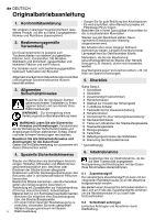
en ENGLISH 7. Use 8. Cleaning, Maintenance 7.1 Duo oscillating circuit setting (only with SXE 450 TurboTec) You can choose between two oscillating frequency settings: • Oscillating circuit high setting (6.2 mm): coarse sanding with high material removal rate • Oscillating circuit low setting (2.8 mm): fine sanding, polishing Changing oscillating circuit: - Disconnect the mains plug! - Press in the locking button (9) and hold in place. - Rotate support plate (2) in a counter-clockwise direction until you can hear it engage. - Continue holding in the button. - Continue turning the support plate half a revolution to the next snap-in point. - Release the locking button. 7.2 On/Off switch, continuous activation To start the machine, press the trigger switch (8). For continuous operation the trigger switch can be locked using the lock button (7). To stop the machine, press the trigger switch (8) again. 7.3 Setting oscillating frequency When the TurboBoost switch (6) is switched off, the oscillating speed can be set at the setting wheel (5). This is also possible during operation. Recommended oscillating frequency settings: Plastic materials 1-2 Metal, Plexiglas®, old coats of paint. . . . . 3-4 Coarse and fine sanding, polishing, wood 5 The best way to determine the ideal setting is through a practical trial. 7.4 TurboBoost switch Empty dust collection box (12). - Open cleaning flap (13). - Empty dust collection box (12). - Remove fluted filter (14) and knock off dust stuck to filter or remove with brush. - When inserting, ensure that the fluted filter (14) is inserted in the lateral guides. The clean the machine regularly, frequently and thoroughly. Vacuum clean the ventilation slots on the motor or blow compressed air through the ventilation slots. Hold the machine firmly at the same time. Replacing a worn support plate Note: If abrasive material (e.g. filled or painted surfaces, etc.) is being sanded, the support plate inevitably wears faster. - Use the hexagon spanner (10) to unscrew the fixing screw (15) on the support plate. - Remove support plate (2). - For replacement support plates, refer to the Accessories chapter. - Mount support plate (2) and rotate until it engages on carrier disc. - Insert locking screw (15) again and tighten. Replacing support plate brake / braking ring If the idling speed of the support plate increases in course of time, the braking ring (16) is worn and must be replaced. Note: If abrasive material (e.g. filled or painted surfaces, etc.) is being sanded, the braking ring inevitably wears faster. - Use the hexagon spanner (10) to unscrew the fixing screw (15) on the support plate. - Remove support plate (2). - Replace the old braking ring (16) with the new braking ring (see Chapter on Accessories), ensuring that the new braking ring is in the same position as the old braking ring. Ensure that the position of the marking on the braking ring is correct. - Mount support plate (2) and rotate until it engages on carrier disc. - Insert locking screw (15) again and tighten. Actuate the TurboBoost switch (6) during operation to switch on additional power reserves for maximum material removal rate. 7.5 Dust extraction To optimise the dust extraction performance, fit the sanding disc such that the holes on the sanding disc (1) are aligned to the support plate (2). Own extraction system: Fit the dust collection box (12) onto the exhaust nozzle until it engages. To remove, press the button (11) and pull off the dust collection box (12) to the rear. To optimise the extraction performance, empty the dust collection box (12) in good time and clean the filter (14). 9. Tips and Tricks Do not press the device too firmly against the surface being sanded. This does not improve, but rather impairs, the sanding performance. To optimise the extraction performance, empty the dust collection box (12) in good time and clean the fluted filter (14).english Use a suitable sanding disc to achieve the best possible work results: Removal of old paint layers = P 40 Pre-sanding of wood = P 60, P 80 Finishing of wood = P 100, P 120 Sanding of veneers, sealing primer, filler, paint = P 180, P 240, P 320, P 400 External extraction system: Connect a suitable extraction device. 8
-
 1
1 -
2
-
 3
3 -
 4
4 -
 5
5 -
 6
6 -
 7
7 -
 8
8 -
 9
9 -
 10
10 -
 11
11 -
 12
12 -
 13
13 -
14
-
15
-
16
-
17
-
18
-
19
-
20
-
21
-
22
-
23
-
24
-
25
-
26
-
27
-
28
-
29
-
30
-
31
-
32
-
33
-
34
-
35
-
36
-
37
-
38
-
39
-
40
-
41
-
42
-
43
-
44
-
45
-
46
-
47
-
48
-
49
-
50
-
51
-
52
-
53
-
54
-
55
-
56
 |
 |
