Metabo WE 1450-125 RT Operating Instructions 2 - Page 15
Commissioning, Attaching the grinding wheel
 |
View all Metabo WE 1450-125 RT manuals
Add to My Manuals
Save this manual to your list of manuals |
Page 15 highlights
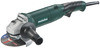
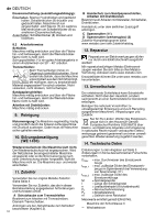
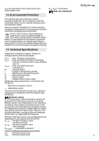
10 Safety cover 11 Clamping nut * 12 2-hole spanner * 13 Clamping screw * depending on equipment/not in scope of delivery 6. Commissioning Before plugging in, check to see that the rated mains voltage and mains frequency, as stated on the rating label, match your power supply. 6.1 Attaching the additional handle Always work with the additional handle attached (9)! Attach the additional handle on the left or right of the machine and secure. 6.2 Install safety guard For safety reasons, always use the safety guard provided for the respective wheel! See also chapter 11. Safety guard for grinding Designed for work with roughing wheels, flap sanding pads, diamond cut-off wheels. See page 2, illustration C. - Slacken the screw (13). Place the safety guard (10) in the position indicated. - Turn the safety guard until the closed section is facing the operator. - Tighten the screw (13), ensuring that the anti-twist device engages in the slots. - Make sure that the guard is seated securely: you should not be able to turn the safety guard. Use only accessories that are covered by at least 3.4 mm by the safety guard. 7. Attaching the grinding wheel Disconnect the mains plug before changing any accessories. The machine must be switched off and the spindle at a standstill. For reasons of safety, attach the parting guard before performing parting work (see chapter 11. Accessories). 7.1 Locking the spindle - Press in the spindle locking button (5) and turn the spindle (4) by hand until the spindle locking button engages. 7.2 Placing the grinding wheel in position See page 2, illustration A. - Place the supporting flange (3) on the spindle (see illustration above). The flange should not turn on the spindle when properly attached. - Place the grinding wheel on the support flange (3) (see illustration above). The grinding wheel must lay flat on the supporting ENGLISH en flange. The metal flange on the parting grinder disc must lay flat on the support flange. Note: The support flange (3) is secured to prevent it from falling off. To remove: use some force if necessary. 7.3 Securing/releasing the (tool-free) clamping nut (depending on features) Only tighten the (tool-free) clamping nut (2) manually. For the machine to operate, the clip (1) must always lie flat on clamping nut (2) . To secure the (tool-free) clamping nut (2): Do not use the (tool-free) clamping nut if the accessory has a clamping shank thicker than 6 mm! In this case, use the clamping nut (11) with 2hole spanner (12). - Lock the spindle (see chapter 7.1). - Flip up the clip (1) on the clamping nut. - Fit the clamping nut (2) on the spindle (4). See illustration on page 2. - (1)Tighten the clamping nut on the clip manually in a clockwise direction. - Flip down the clip (1) again . To release the (tool-free) clamping nut (2) : - Lock the spindle (see chapter 7.1). - Flip up the clip (1) on the clamping nut. - Unscrew the clamping nut (2) , turning it anticlockwise manually . Note: If the clamping nut is very tightly secured (2), you can also use a 2-hole spanner to unscrew it. 7.4 Securing/releasing the clamping nut (depending on features) Securing the clamping nut (11): The 2 sides of the clamping nut are different. Screw the clamping nut onto the spindle as follows: See page 2, illustration B. - A) For thin grinding wheels: The edge of the clamping nut (11) faces upwards so that the thin grinding wheel can be attached securely. B) For thick grinding wheels: The edge of the clamping nut (11) faces downwards so that the clamping nut can be attached securely to the spindle. - Lock the spindle. Turn the clamping nut (11) clockwise using the 2-hole spanner (12) to secure. Releasing the clamping nut: - Lock the spindle (see chapter 7.1). Turn the clamping nut (11) anticlockwise using the 2-hole spanner (12) to unscrew. 8. Use 8.1 Switching On and Off Always guide the machine with both hands. 15
-
 1
1 -
2
-
3
-
4
-
5
-
6
-
7
-
8
-
9
-
 10
10 -
 11
11 -
 12
12 -
 13
13 -
 14
14 -
 15
15 -
 16
16 -
 17
17 -
 18
18 -
 19
19 -
 20
20 -
21
-
22
-
23
-
24
-
25
-
26
-
27
-
28
-
29
-
30
-
31
-
32
-
33
-
34
-
35
-
36
-
37
-
38
-
39
-
40
-
41
-
42
-
43
-
44
-
45
-
46
-
47
-
48
-
49
-
50
-
51
-
52
-
53
-
54
-
55
-
56
-
57
-
58
-
59
-
60
-
61
-
62
-
63
-
64
-
65
-
66
-
67
-
68
-
69
-
70
-
71
-
72
-
73
-
74
-
75
-
76
-
77
-
78
-
79
-
80
-
81
-
82
-
83
-
84
-
85
-
86
-
87
-
88
-
89
-
90
-
91
-
92
-
93
-
94
-
95
-
96
-
97
-
98
-
99
-
100
-
101
-
102
-
103
-
104
 |
 |