Milwaukee Tool M18 FUEL 1/2" Hammer Drill/Driver Service Parts List - Page 1
Milwaukee Tool M18 FUEL 1/2" Hammer Drill/Driver Manual
 |
View all Milwaukee Tool M18 FUEL 1/2" Hammer Drill/Driver manuals
Add to My Manuals
Save this manual to your list of manuals |
Page 1 highlights
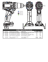
FIG. PART NO. 1 05-88-0019 2 12 06-82-7337 19 42-92-7012 20 06-82-6351 22 23 24 42-42-7003 25 06-82-2367 26 27 06-82-2500 28 29 44-10-0160 30 45-24-2670 31 59 44-10-4020 19 SERVICE PARTS LIST BULLETIN NO. 54-24-2990 SPECIFY CATALOG NO. AND SERIAL NO. WHEN ORDERING PARTS M18™ FUEL™ Brushless Hammer-Drill CATALOG NO. 2904-20 STARTING SERIAL NO. M64A REVISED BULLETIN DATE Aug. 2022 WIRING INSTRUCTION SEE PAGE 2 DESCRIPTION OF PART NO. REQ. M8.0 x 1 LH T-40 Chuck Screw (1) 1/2" Keyless Chuck (1) M4 x 20mm Pan Hd. ST T-10 w/Washer Scr.(4) Back Cap (1) M3 x 16mm Pan Hd. ST T-10 Screw (9) Lens (1) Right Housing Halve - Cover (1) Forward/Reverse Shuttle (1) M3 x 38mm Pan Hd. ST T-10 Screw (2) Bit Holder (1) #6-32 x 7mm Pan Hd. Machine Screw (2) Belt Clip (1) Detent Spring (1) Speed Selector (1) Left Housing Halve - Support (1) Shift Spring (1) 00 0 EXAMPLE: Component Parts (Small #) Are Included When Ordering The Assembly (Large #). See page 3 for fastener tightening procedure and torque specifications. 64 20 31 23 62 25 76 (240x) 68 70 Note: QR codes are not user-replaceable. 30 Return your tool to a Milwaukee Authorized Repair Center for QR 71 31 code replacement. 69 59 23 62 24 29 27 65 27 28 28 67 1 2 72 * 2 20 (5x) 26 See detail on page 2 63 26 27 27 75 22 66 12 76 22 75 (4x) 77 12 59 29 66 30 1 See instructions below on how to remove the chuck screw and chuck REMOVING THE CHUCK SCREW: Set the Speed Selector Slide to the #1 setting. With the aid of a small pencil tip torch (or use an air reduction nozzle on a heat gun) apply heat into the chuck opening, directly to the head of reversing screw just prior to removing the screw. Place a T40 1/4" torx bit into the head of the reversing screw and place a 1/4" boxed end wrench over the hex on the T40 bit. It is recommended to use a 12"-18" metal tube or pipe as leverage over the boxed wrench. In a clockwise direction apply a slow, steady force on the 'cheater bar' to break the screw loose. FIG. PART NO. 62 12-20-9095 63 49-16-3697 64 31-44-7060 65 42-70-0950 66 67 42-66-2720 68 16-07-2983 69 14-20-6560 70 42-62-0550 71 42-55-9020 72 75 76 31-44-7008 77 14-29-5015 25(2x) DESCRIPTION OF PART Service Nameplate Bit Holder Kit (Accessory) Housing Service Assembly Belt Clip Service Kit Gearbox 1/2" Keyless Chuck Rotor Service Assembly Electronic Service Assembly Side Handle Service Assembly Blow Molded Carrying Case QR Code Label Auto-Stop Label Lens/Label Assembly Gearbox Service Assembly NO. REQ. (1) (1) (1) (1) (1) (1) (1) (1) (1) (1) (1) (1) (1) (1) REMOVING THE KEYLESS CHUCK: Tighten a 3/8" or 10mm Allen Key into the jaws of the chuck. Place the tool into a vise with soft jaws (this will require that you remove the belt clip from the tool). It is recommended to use a 12"-18" metal tube or pipe as leverage over the allen key. In a counter-clockwise direction apply a slow, steady force on the 'cheater bar' to break the chuck loose. INSTALLING NEW CHUCK AND SCREW: Torque Chuck to 1095 kg/cm (950.418 in/lbs or 79.20 ft/lbs) Torque Screw to 400 kg/cm (347 in/lbs or 28.93 ft/lbs) MILWAUKEE TOOL l www.milwaukeetool.com 13135 W. Lisbon Rd., Brookfield, WI 53005 Drwg. 3
-
 1
1 -
 2
2 -
 3
3
 |
 |
