NEC E321 MultiSync LCD5710-2-AV : WMK-3257 accessory guide - Page 7
Mounting and Removing Flat Panel Screen, DETAIL 2, fig 4.1, Adjusting the Tilt Angle of the Flat, - driver
 |
UPC - 805736032819
View all NEC E321 manuals
Add to My Manuals
Save this manual to your list of manuals |
Page 7 highlights
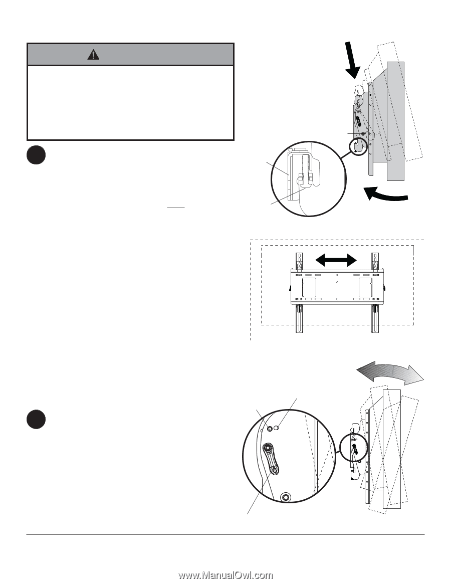
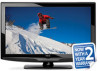
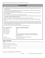
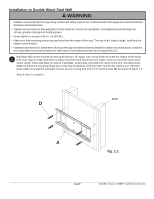
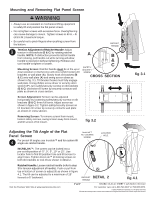
Mounting and Removing Flat Panel Screen WARNING • Always use an assistant or mechanical lifting equipment to safely lift and position the flat panel screen. • Do not tighten screws with excessive force. Overtightening can cause damage to mount. Tighten screws to 40 in. • lb (4.5 N.M.) maximum torque. • Be careful not to pinch fingers when pushing screen from the bottom. 3 Tension Adjustment of Ratchet Handle: Adjust tension in tilt brackets (B & C) by rotating ratchet handle. NOTE: If obstruction prevents ratchet handle from rotating, pull handle out while turning will allow handle to reposition without tightening. Release and turn handle to tighten or loosen. Mounting Screen: Ratchet handle must be in the up or down position or interference will occur while hooking tilt brackets to wall plate (A). Slowly hook tilt brackets (B & C) onto wall plate (A) and swing screen down as shown in fig. 3.1. Tilt bracket hooks must fully engage wall plate. Using phillips screw driver or security allen wrench (F), turn safety/security screws on tilt brackets (B & C) clockwise till screw tip securely contacts wall plate as shown in cross section. RATCHET HANDLE A B & C SAFETY/ SECURITY SCREW CROSS SECTION Screen Adjustment: Screen can be adjusted horizontally by loosening safety/security screws on tilt brackets (B & C) three full turns. Adjust screen as shown in figure 3.2. Tighten safety/security screws on tilt brackets till screw tip securely contacts wall plate as shown in cross section. Removing Screen: To remove screen from mount, loosen safety screws, swing screen away from mount, and lift screen off of mount. fig 3.2 fig 3.1 Adjusting the Tilt Angle of the Flat Panel Screen 4 For preset tilt angles use Increlok™ and for custom tilt angle use ratchet handle. IncreLok™ TILT LOCKING SCREW LOCATOR HOLE INCRELOK™: The screen can be locked into a pre-set tilt position of -5°, 0°, 5°, 10° or 15°. Use locator hole to find tilt position hole and tilt screen to align holes. Tighten IncreLok™ tilt locking screws on both tilt brackets to lock tilt as shown in detail 2. Ratchet Handle: Loosen ratchet handle (refer to step 3 for tension adjustment of handle). Push or pull from top or bottom of screen to adjust tilt as shown in figure 4.1. The tilt can be adjusted to a maximum of 15° forward or 5° backward. RATCHET DETAIL 2 HANDLE fig 4.1 Visit the Peerless Web Site at www.peerlessmounts.com 7 of 7 ISSUED: 03-26-10 SHEET #: 125-9106-3 08-04-10 For customer care call 1-800-729-0307 or 708-865-8870. © 2009, Peerless Industries, Inc. All rights reserved. All other brand and product names are trademarks or registered trademarks of their respective owners.
-
 1
1 -
 2
2 -
 3
3 -
 4
4 -
 5
5 -
 6
6 -
 7
7
 |
 |