NEC NP400 NP310 : NP600CM Mount Instructions - Page 6
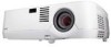
Installation to Concrete Ceilings, fig. 2.6
 |
UPC - 805736024401
View all NEC NP400 manuals
Add to My Manuals
Save this manual to your list of manuals |
Page 6 highlights
Installation to Concrete Ceilings WARNING • Tighten wood screws firmly, but do not overtighten. Overtightening can damage the screws, greatly reducing their holding power. • Never tighten in excess of 80 in • lb (9 N.M.). 2 Place projector mount assembly (A) on ceiling as a template and mark the center of the two mounting holes. Drill two 1/4" (6 mm) dia. holes to a minimum depth of 2.5" (64 mm). Attach projector mount assembly (A) using two concrete anchors (G), two flat washers (E), and two #14 x 2.5" wood screws (F) as shown in fig. 2.6 and 1, 2 and 3 (right). Tighten wood screws (F) using 3/8" (10 mm) socket wrench, phillips screwdriver or 10mm open end wrench until projector mount assembly (A) is firmly attached. NOTE: It is the responsibility of the installer to verify that the ceiling will safely support the combined load of all attached hardware and components. 1 concrete ceiling G Drill holes and insert anchors 2 A FG Skip to step 3. WARNING Place mount over anchors and secure with screws 3 • Concrete anchors are not intended for attachment to concrete ceiling covered with a layer of plaster, drywall, or other finishing material. If mounting to concrete ceiling covered with plaster/drywall is unavoidable, plaster/drywall (up to 5/8" thick) must be counterbored as shown below. If plaster/drywall is thicker than 5/8", custom fasteners must be supplied by installer. Tighten all fasteners FG INCORRECT A concrete CORRECT A concrete CONCRETE CEILING CUTAWAY VIEW plaster/ dry wall plaster/ dry wall Visit the Peerless Web Site at www.peerlessmounts.com 6 of 10 G FRONT OF MOUNT A E F fig. 2.6 ISSUED: 08-05-08 SHEET #: 056-9008-1 For customer care call 1-800-865-2112 or 708-865-8870.
-
 1
1 -
 2
2 -
 3
3 -
 4
4 -
 5
5 -
 6
6 -
 7
7 -
 8
8 -
 9
9 -
 10
10
 |
 |
