NEC PX-50XR6A 42XR5/50XR5/60XR5 speaker manual - Page 6
Attaching speakers to a, inch plasma monitor
 |
View all NEC PX-50XR6A manuals
Add to My Manuals
Save this manual to your list of manuals |
Page 6 highlights
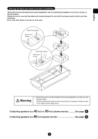
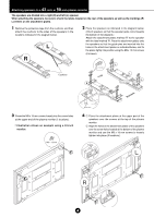
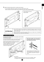
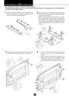
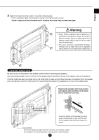
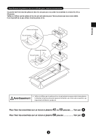
60 Attaching speakers to a -inch plasma monitor The speakers are divided into a right (R) and left (L) speaker. When attaching the speakers, be sure to check the labels located on the rear of the speakers as well as the markings (R/ L) written on the attachment plates. 1 Remove the protective tape from the cushions and then attach the cushions to the sides of the speakers in the locations indicated in the diagram below. 2 Place the speakers as indicated in the diagram below. (Orient speakers so that the speaker jacks come towards the bottom of the diagram.) Attach the attachment plates marked 'TR' to the speaker with the label marked 'R'. Place the attachment plates onto the speakers so that the guide pins are inserted into the holes in the attachment plates as indicated below, and fix the plates tightly into position using the M4 x 10 mm screws (8 screws). Cushions TL M4 × 10 mm L BL L TR R R BR Speaker jacks Speaker jacks 3 Screw the M5 x 12 mm screws loosely into the screw holes at the upper end of the plasma monitor (2 locations). M5 × 12 mm Guide pins 4 1 Place the attachment plates at the upper part of the speakers over the screws at the top of the plasma monitor. 2 Align the holes of the attachment plates of the speakers over the screw holes located at the bottom of the plasma monitor and use the M5 x 12 mm screws to loosely tighten into place (2 locations). 6
-
 1
1 -
 2
2 -
 3
3 -
 4
4 -
 5
5 -
 6
6 -
 7
7 -
 8
8 -
 9
9 -
 10
10 -
 11
11 -
 12
12 -
13
-
14
-
15
-
16
 |
 |
