NEC VT440 User Manual - Page 16
Ceiling Installation
 |
UPC - 050927232169
View all NEC VT440 manuals
Add to My Manuals
Save this manual to your list of manuals |
Page 16 highlights
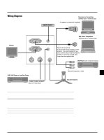
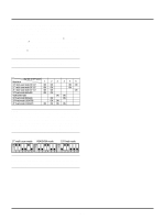
Ceiling Installation F B α PC-CONTROL S-VIDEO VIDEO RGB INPUT OUTPUT AUDIO IN OUT OUT IN A C A: Distance between the lens and the screen center B: Vertical distance between the top of the supplied ceiling mount and the screen center C: Horizontal throw distance between screen surface and the lens F: Vertical distance between projector base and top of image Formulas(mm) H" = Horizontal Screen Width (inch) A = C/cosα B = 94 + 5.5 × M C (wide) = 36.8712 × (diagonal screen size/ 0.92205) - 43.5689 C (tele) = C(wide) × 1.2 F = 1.4516 × M - 94 M = 1.25H" / 22.86 Formulas(inch) H" = Horizontal Screen Width A = C/cosα B = (T.B.D. +5.5 × M) / 25.4 C (wide) = (36.8712 × (diagonal screen size/0.92205) - 43.5689) / 25.4 C (tele) = C (wide) × 1.2 F = 1.4516 × M - 94/25.4 M = 1.25H / 0.9 Zoom Lens (Wide) α β (=sinα) γ (=cosα) Screen Size H-Width 4:3 Diagonal A C B F degree inch inch mm inch mm inch mm inch mm inch 9.01 0.16 0.99 24 30 1171 46 1156 46 277 11 -46 -2 Zoom Lens (Tele) α β (=sinα) γ (=cosα) Screen Size H-Width 4:3 Diagonal A C B F degree inch inch mm inch mm inch mm inch mm inch 6.28 0.11 0.99 20 25 1396 55 1387 55 247 10 -54 -2 8.93 0.16 0.99 32 40 1471 58 1452 57 338 13 -29 -1 7.1 0.12 0.99 32 40 1902 75 1887 74 338 13 -29 -1 8.85 0.15 0.99 48 60 2242 88 2214 87 461 18 3 0 7.0 0.12 0.99 48 60 2900 114 2878 113 461 18 3 0 8.82 0.15 0.99 56 70 2628 103 2595 102 522 21 19 1 7.0 0.12 0.99 56 70 3399 134 3373 133 522 21 19 1 8.81 0.15 0.99 64 80 3013 119 2976 117 583 23 35 1 7.0 0.12 0.99 64 80 3898 153 3869 152 583 23 35 1 8.79 0.15 0.99 72 90 3399 134 3357 132 644 25 51 2 7.0 0.12 0.99 72 90 4397 173 4364 172 644 25 51 2 8.78 0.15 0.99 80 100 3785 149 3738 147 705 28 67 3 6.9 0.12 0.99 80 100 4896 193 4860 191 705 28 67 3 8.77 0.15 0.99 96 120 4556 179 4500 177 827 33 100 4 6.9 0.12 0.99 96 120 5893 232 5851 230 827 33 100 4 8.75 0.15 0.99 120 150 5713 225 5644 222 1011 40 148 6 6.9 0.12 0.99 120 150 7390 291 7337 289 1011 40 148 6 8.74 0.15 0.99 144 180 6870 270 6787 267 1194 47 196 8 6.9 0.12 0.99 144 180 8887 350 8823 347 1194 47 196 8 8.74 0.15 0.99 160 200 7641 301 7549 297 1316 52 229 9 8.73 0.15 0.99 192 240 9184 362 9074 357 1561 61 293 12 8.72 0.15 0.99 216 270 10341 407 10217 402 1744 69 341 13 8.72 0.15 0.99 240 300 11498 453 11360 447 1927 76 390 15 6.9 0.12 0.99 160 200 9885 389 9814 386 1316 52 229 9 6.9 0.12 0.99 192 240 11881 468 11796 464 1561 61 293 12 6.9 0.12 0.99 216 270 13378 527 13282 523 1744 69 341 13 6.9 0.12 0.99 240 300 14875 586 14768 581 1927 76 390 15 WARNING • Installing your projector on the ceiling must be done by a quali- fied technician. Contact your NEC dealer for more information. * Do not attempt to install the projector yourself. • Only use your projector on a solid, level surface. If the projector falls to the ground, you can be injured and the projector severely damaged. • Do not use the projector where temperatures vary greatly. The projector must be used at temperatures between 32˚F (0˚C) and 95˚F (35˚C). • Do not expose the projector to moisture, dust, or smoke. This will harm the screen image. • Ensure that you have adequate ventilation around your projector so heat can dissipate. Do not cover the vents on the side or the front of the projector. If your projector is mounted on the ceiling and your image is upside down, use the "Menu" and "Select" buttons on your projector cabinet or vw button on your remote control to correct the orientation. (See page E-31.) Reflecting the Image Using a mirror to reflect your projector's image enables you to enjoy a much larger image. Contact your NEC dealer if you need a mirror. If you're using a mirror and your image is inverted, use the "Menu" and "Select" buttons on your projector cabinet or vw buttons on your remote control to correct the orientation. (See page E-31.) E-16
-
 1
1 -
2
-
3
-
4
-
5
-
6
-
7
-
8
-
9
-
10
-
 11
11 -
 12
12 -
 13
13 -
 14
14 -
 15
15 -
 16
16 -
 17
17 -
 18
18 -
 19
19 -
 20
20 -
 21
21 -
22
-
23
-
24
-
25
-
26
-
27
-
28
-
29
-
30
-
31
-
32
-
33
-
34
-
35
-
36
-
37
-
38
-
39
-
40
 |
 |
