Nady CX-22SW Manual - Page 4
Controls And Connections - stereo crossover
 |
View all Nady CX-22SW manuals
Add to My Manuals
Save this manual to your list of manuals |
Page 4 highlights
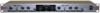
CONTROLS AND CONNECTIONS 2 3 6 2 4 4 FRONT PANEL 5 7 8 1. POWER SWITCH To turn the unit ON or OFF, press the upper or lower portion of this button. The internal power LED illuminates when the unit is turned "ON". (Caution: Always turn the Crossover ON before the amplifier, and turn it OFF after the amplifier or transients harmful to the speakers may result.) 2. CROSSOVER FREQUENCY CONTROLS: These select the crossover frequencies of the LOW and HIGH ways. They're a low cut for the HIGH and a high cut for the LOW. You can select the frequencies between 250 Hz and 6 Hz. 3 5 1 PLEASE READ THIS MANUAL BEFORE OPERATING THIS UNIT Caution : To prevent malfunctioning and/or possible equipment damage: Before plugging the unit into the power source: (1) the voltage selector switch should be set for the correct voltage for your area (115V or 230V) and (2) all equipment connected to the crossover outputs should be turned off or all the inputs turned down. 3. L/H OUTPUT LEVEL CONTROLS: These are used to adjust the output level of each way: LOW and HIGH . 4. LOW CUT BUTTONS FOR LOW WAY: These insert low cut filters in the LOW way of each stereo channel with a 12dB/Octave, 30 Hz HPF to minimize problems from subsonic frequencies in the signal, to suppress hum, and to prevent low frequency speaker resonance. 5. PHASE BUTTONS: These allow switching the polarity to invert the signal phase on the HIGH ways. This is done after the output levels are set to correct audible phase problems. Caution: Before pressing the PHASE BUTTON, always lower the outputs of your power amplifiers to avoid possible speaker damage. 6. SUB CROSSOVER FREQUENCY CONTROL: This selects the crossover frequency of the SUB WOOFER way. You can select the frequency between 50 Hz to 250 Hz. 7. SUBWOOFER OUTPUT LEVEL CONTROL: This is used to adjust the SUB WOOFER output level. 8. SUBWOOFER LOW CUT BUTTON: This inserts a low cut filter in the SUBWOOFER way with a 12dB/Octave, 30 Hz HPF to minimize problems from subsonic frequencies in the signal, to suppress hum, and to prevent low frequency subwoofer speaker resonance. 4
-
 1
1 -
 2
2 -
 3
3 -
 4
4 -
 5
5 -
 6
6 -
 7
7
 |
 |
