Netgear DS508 DS508 Installation Guide - Page 7
Site Preparation
 |
UPC - 606449001570
View all Netgear DS508 manuals
Add to My Manuals
Save this manual to your list of manuals |
Page 7 highlights
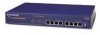
vista RJ-45 network ports 100M 10M 8152FA Rear Panel of the Model DS508, Model DS516, and Model DS524 Hubs Cascade Up connector Terminator LED 10/100 Mbps Bridge LED Power receptacle Cascade Up Cascade Down 10/100 Mbps Terminator Bridge 100-240 VAC 50-60 Hz 0.5A Cascade Down connector 8153FA Rear Panel The rear panel of a Model DS508, Model DS516, and Model DS524 hub has two LEDs, one labeled Terminator and one labeled 10/100 Mbps Bridge. The Terminator LED indicates whether or not the built-in terminator in that hub is active (the built-in terminator eliminates the need for an external terminator). The 10/100 Mbps Bridge LED indicates which hub has the active bridge. Site Preparation Before you begin installing the hubs, prepare the installation site. Make sure your operating environment meets the operating environment requirements of the equipment. Characteristic Requirement Temperature Humidity Ventilation Operating conditions Service access Power Tabletop requirements Ambient temperature between 0° and 40° C (32° and 104° F). No nearby heat sources such as direct sunlight, warm air exhausts, or heaters. 90% maximum relative humidity, noncondensing. Minimum 2 inches (5.08 cm) on all sides for cooling. Adequate airflow in room or wiring closet. At least 6 feet (1.83 m) to nearest source of electromagnetic noise (such as photocopy machine or arc welder). Minimum 12 inches (19.68 cm) front and back for service access and maintenance. Front and back clearance for cables and wiring hardware such as punchdown blocks. Adequate power source within 6 feet (1.83 m). Flat area approximately 13.0 inches (33.0 cm) by 8.0 inches (20.3 cm). Model DS508/DS516/DS524 Dual Speed Stackable Hub Installation Guide
-
 1
1 -
 2
2 -
 3
3 -
 4
4 -
 5
5 -
 6
6 -
 7
7 -
 8
8 -
 9
9 -
 10
10 -
 11
11 -
 12
12 -
13
-
14
-
15
-
16
 |
 |
