Netgear FSM7250RS FSM7226RS / FSM7250RS Hardware Installation Guide - Page 12
FSM7226RS Rear Panel, FSM7250RS Front Panel and LEDs
 |
UPC - 606449059946
View all Netgear FSM7250RS manuals
Add to My Manuals
Save this manual to your list of manuals |
Page 12 highlights
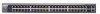
Managed Layer 2+ Stackable Switches FSM7226RS and FSM7250RS Hardware Installation Guide FSM7226RS Rear Panel The rear panel has two stacking ports, a console port, redundant power supply connector, and a standard AC power receptacle for the supplied power cord. Stacking ports Power receptacle Console port Figure 1-2 Redundant power supply connector FSM7250RS Front Panel and LEDs The following figure shows the front panel of the managed switch. The front panel contains LEDs, a RST (reset) button, RJ-45 jacks, and copper/fiber combo ports. RST LEDs (reset button) Figure 1-3 RJ-45 jacks Copper/fiber combo ports 1-2 Introduction v1.0, October 2008
-
 1
1 -
2
-
3
-
4
-
5
-
6
-
 7
7 -
 8
8 -
 9
9 -
 10
10 -
 11
11 -
 12
12 -
 13
13 -
 14
14 -
 15
15 -
 16
16 -
 17
17 -
18
-
19
-
20
-
21
-
22
-
23
-
24
-
25
-
26
-
27
-
28
-
29
-
30
-
31
-
32
-
33
-
34
 |
 |

Managed Layer 2+ Stackable Switches FSM7226RS and FSM7250RS Hardware Installation Guide
1-2
Introduction
v1.0, October 2008
FSM7226RS Rear Panel
The rear panel has two stacking ports, a console port, redundant power supply connector, and a
standard AC power receptacle for the supplied power cord.
Power receptacle
Console port
Redundant
power supply connector
Stacking ports
Figure 1-2
FSM7250RS Front Panel and LEDs
The following figure shows the front panel of the managed switch. The front panel contains LEDs,
a RST (reset) button, RJ-45 jacks, and copper/fiber combo ports.
Copper/fiber
RJ-45 jacks
LEDs
combo ports
RST
(reset button)
Figure 1-3