Netgear FSM7326P FSM7326P Hardware manual - Page 13
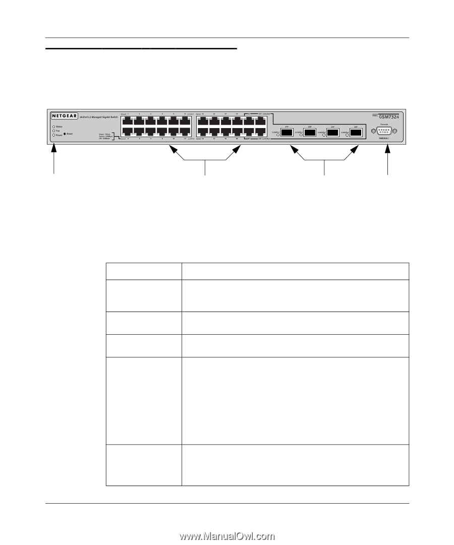
GSM7324 Front Panel and LEDs, contains LEDs, RJ-45 jacks, SFP module bays, and a console.
 |
UPC - 606449031072
View all Netgear FSM7326P manuals
Add to My Manuals
Save this manual to your list of manuals |
Page 13 highlights
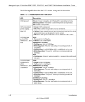
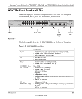
Managed Layer 3 Switches FSM7326P, GSM7312, and GSM7324 Hardware Installation Guide GSM7324 Front Panel and LEDs The following figure shows the front panel of the GSM7324. The front panel contains LEDs, RJ-45 jacks, SFP module bays, and a console. LEDs Figure 2-5 RJ-45 jacks SFP module bays Console port The following table describes the GSM7324 LEDs on the front of the switch. Table 2-3. GSM7324 LED Description LED Power Fan Status 10/100/1000 Mbps port: Link/Act SPF port (1,000 Mbps only) Description • Green: Power supply is present and operating normally. • Yellow: Power supply is present, but failed. • Off: Power supply is not present. • Red: Fan has failed. • Off: Fan is working. • Green: Switch is operating normally. • Yellow: Switch has failed to boot up. Link (left) • Green: Link in 1,000 Mbps. • Yellow: Link in 100 Mbps. • Off: Link in 10 Mbps. Act (right) • Solid green: Link up. • Blinking green: Activity, transmitting or receiving a packet in link up state. • Off: No link detected. • Solid green: Link up. • Blinking green: Activity, transmitting or receiving a packet in link up state. • Off: No link detected. Introduction 2-5 v1.0, March 2006
-
 1
1 -
2
-
3
-
4
-
5
-
6
-
7
-
 8
8 -
 9
9 -
 10
10 -
 11
11 -
 12
12 -
 13
13 -
 14
14 -
 15
15 -
 16
16 -
 17
17 -
 18
18 -
19
-
20
-
21
-
22
-
23
-
24
-
25
-
26
-
27
-
28
-
29
-
30
-
31
-
32
-
33
-
34
-
35
-
36
-
37
-
38
 |
 |