Netgear GS724TPS GS7xxTPS Hardware manual - Page 24
Software Administrator User Guide, User Guide, Resource CD. - factory reset
 |
UPC - 606449061086
View all Netgear GS724TPS manuals
Add to My Manuals
Save this manual to your list of manuals |
Page 24 highlights
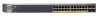
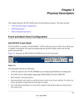
GS700TPS Smart Switch Each unit may work in one of two modes: Stand-alone, or Stack-mode. The operational mode is determined at Boot time of the software, and can only be changed by a unit reset. The stacking 7 Segment LED is not illuminated (off) if the unit is operating in stand-alone mode. At factory default, units boot in Stack mode. This is the default setting. If required, change this setting from the System > Management > System Information screen. Setting the unit mode can be done either by a specific command (Using WEB GUI). There are two stacking topologies supported by the device, the Ring topology or Chain topology. Figure 2-4 The device is "Plug and Play" in terms of stacking configuration. Before powering up the device, connect the devices into the required stacking topology. Power up the devices. The stacking Master and slave designations are configured through automatic discovery. Manually changing the stacking configuration is through switch's web page once the device has been booted and is operational. For more information on stacking see the Software Administrator User Guide. A link to the User Guide is on your Resource CD. 2-6 Installation v1.0, April 2009
-
 1
1 -
2
-
3
-
4
-
5
-
6
-
7
-
8
-
9
-
10
-
11
-
12
-
13
-
14
-
15
-
16
-
17
-
18
-
 19
19 -
 20
20 -
 21
21 -
 22
22 -
 23
23 -
 24
24 -
 25
25 -
 26
26 -
 27
27 -
 28
28 -
 29
29 -
30
-
31
-
32
-
33
-
34
-
35
-
36
-
37
-
38
-
39
-
40
-
41
-
42
-
43
-
44
 |
 |
