Netgear M4100-12GF Hardware Installation Guide - Page 10
Safety Instructions, Observe and follow service markings.
 |
View all Netgear M4100-12GF manuals
Add to My Manuals
Save this manual to your list of manuals |
Page 10 highlights
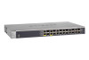
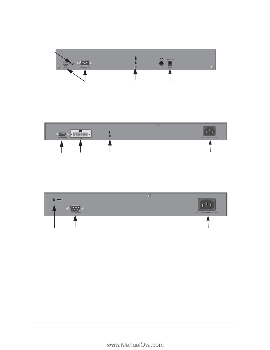
NETGEAR Managed Switch Console switch Console ports Lock Power adapter connector Figure 14. M4100-D10-POE and M4100-D12G rear panels Console port RPS Lock power supply connector Figure 15. M4100-12GF, 24G-POE+, 12G-POE+ rear panel AC power connector Lock Console port Figure 16. M4100-D12G-POE+ rear panel AC power connector Safety Instructions Use the following safety guidelines to ensure your own personal safety and to help protect your system from potential damage. To reduce the risk of bodily injury, electrical shock, fire, and damage to the equipment, observe the following precautions. • Observe and follow service markings. - Do not service any product except as explained in your system documentation. 10
-
 1
1 -
2
-
3
-
4
-
 5
5 -
 6
6 -
 7
7 -
 8
8 -
 9
9 -
 10
10 -
 11
11 -
 12
12 -
 13
13 -
 14
14 -
 15
15 -
16
-
17
-
18
-
19
-
20
-
21
-
22
-
23
-
24
-
25
-
26
-
27
-
28
-
29
-
30
-
31
-
32
-
33
-
34
 |
 |
10
NETGEAR Managed Switch
Figure 14. M4100-D10-POE and M4100-D12G rear panels
Figure 15. M4100-12GF, 24G-POE+, 12G-POE+ rear panel
Figure 16. M4100-D12G-POE+ rear panel
Safety Instructions
Use the following safety guidelines to ensure your own personal safety and to help protect
your system from potential damage.
To reduce the risk of bodily injury, electrical shock, fire, and damage to the equipment,
observe the following precautions.
•
Observe and follow service markings.
-
Do not service any product except as explained in your system documentation.
Power adapter
connector
Lock
Console
ports
Console
switch
AC power
connector
Lock
Console
port
RPS
power supply
connector
AC power
connector
Console
port
Lock