Netgear M4100-26G Hardware Installation Guide - Page 6
M4100-26G-POE front panel, M4100-50G-POE+ front panel, M4100-D10-POE
 |
View all Netgear M4100-26G manuals
Add to My Manuals
Save this manual to your list of manuals |
Page 6 highlights
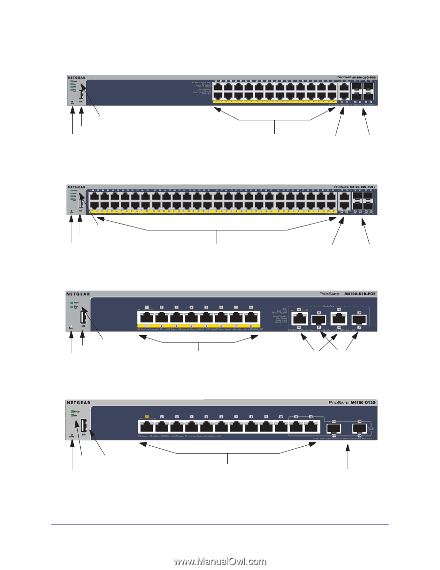
NETGEAR Managed Switch LEDs USB port Reset button Figure 5. M4100-26G-POE front panel POE ports RJ-45 ports SFP ports LEDs USB port Reset button POE ports Figure 6. M4100-50G-POE+ front panel RJ45 ports SFP ports LEDs USB port Reset button POE ports Figure 7. M4100-D10-POE Front Panel RJ45 ports SFP ports LEDs USB port Reset button Figure 8. M4100-D12G front panel RJ45 ports 6 SFP ports
-
 1
1 -
 2
2 -
 3
3 -
 4
4 -
 5
5 -
 6
6 -
 7
7 -
 8
8 -
 9
9 -
 10
10 -
 11
11 -
 12
12 -
13
-
14
-
15
-
16
-
17
-
18
-
19
-
20
-
21
-
22
-
23
-
24
-
25
-
26
-
27
-
28
-
29
-
30
-
31
-
32
-
33
-
34
 |
 |
6
NETGEAR Managed Switch
Figure 5. M4100-26G-POE front panel
Figure 6. M4100-50G-POE+ front panel
Figure 7. M4100-D10-POE Front Panel
Figure 8. M4100-D12G front panel
POE ports
SFP ports
Reset button
LEDs
USB port
RJ-45 ports
LEDs
Reset button
USB port
SFP ports
POE ports
RJ45 ports
POE ports
SFP ports
LEDs
Reset button
USB port
RJ45 ports
SFP ports
USB port
LEDs
Reset button
RJ45 ports