Netgear M4100-26G Hardware Installation Guide - Page 9
Rear Panels, 26G, 50G, 26-POE, 50G-POE+, and 50-POE - 24g poe
 |
View all Netgear M4100-26G manuals
Add to My Manuals
Save this manual to your list of manuals |
Page 9 highlights
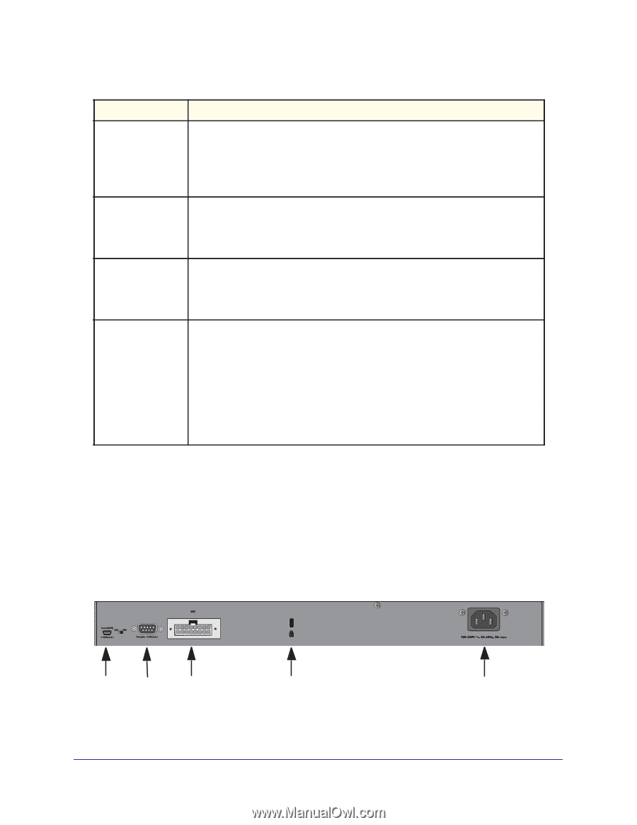
NETGEAR Managed Switch Table 1. LED descriptions (Continued) LED Link/ACT (RJ45 port) SPD (RJ45 port) Description Off: No link is established on the port. Solid green: A valid link is established on the port. Blinking green: Packets transmission or reception is occurring on the port. Note: If a combo port media changes to fiber, the copper port LED changes to off status. Off: No link is established on the port. Solid green: A valid 1000 Mbps link is established on the port. Solid yellow: A valid 10/100 Mbps link is established on the port. PoE-PD Off: No PSE is connected or PSE is connected but connection has failed. Solid green: The PSE is connected and get 30 W power from PSE successfully. Solid yellow: The PSE is connected and get 15.4 W power from PSE successfully. SPD/Link/ACT (SFP port) Off: No SFP/SFP+ module link is established on the port. Solid green: A valid 1000 Mbps SFP+ module link is established on the port. Blinking green: The port is transmitting or receiving packets at 1000 Mbps. Solid yellow: A valid 100 Mbps SFP module link is established on the port. Blinking yellow: Packet transmission or reception is occurring on the port at 100 Mbps. Note: If combo port media changes to copper, the SFP port LED changes to off status. Rear Panels The rear panels have a DB9 console port, a mini USB port (only for M4100-26G, 50G, 26-POE, 26G-POE, 50G-POE+, 50-POE, D12-PoE, and D12G), a redundant power supply connector (only for M4100-26G, 50G, 26-POE, 26G-POE, 50G-POE+, 50-POE, 12GF, 24G-POE+, and 12G-POE+), and a standard AC power receptacle for the supplied power cord. Mini USB port Console port RPS power supply connector Lock AC power connector Figure 13. M4100-26G, 50G, 26-POE, 26G-POE, 50G-POE+, and 50-POE rear panels 9
-
 1
1 -
2
-
3
-
 4
4 -
 5
5 -
 6
6 -
 7
7 -
 8
8 -
 9
9 -
 10
10 -
 11
11 -
 12
12 -
 13
13 -
 14
14 -
15
-
16
-
17
-
18
-
19
-
20
-
21
-
22
-
23
-
24
-
25
-
26
-
27
-
28
-
29
-
30
-
31
-
32
-
33
-
34
 |
 |